Umbrella two-way vertical pump device

A vertical pump, umbrella-shaped technology, applied in non-variable-capacity pumps, components of pumping devices for elastic fluids, pumps, etc., can solve the problems of no rectification measures, large hydraulic loss, etc., and achieve operation management and Ease of maintenance, improved reliability and reduced investment

Active Publication Date: 2015-09-02
YANGZHOU UNIV
View PDF9 Cites 0 Cited by
  • Summary
  • Abstract
  • Description
  • Claims
  • Application Information

AI Technical Summary

Problems solved by technology

These water inlet structure types, water outlet structure types and cut-off methods have been widely used in engineering applications in one-way channel pump devices. So for two-way vertical pump devices, can we learn from the structure types and combine two-way vertical Based on the characteristics of the vertical pump device itself, a new method was invented to overcome the shortcomings of the traditional two-way vertical pump device, such as the vortex belt in the two-way water inlet channel, the complex flow state in the water outlet channel, large hydraulic loss and no rectification measures, etc. Combined with the actual operation of the traditional two-way vertical pumping station, whether it is possible to adopt a cut-off method with simple operation, reliable cut-off, and convenient maintenance, in view of these problems, the significance and application value of designing a new type of two-way vertical pump device It is very large, not only can solve the above problems, but also can improve the inlet conditions of the pump, improve the internal flow state of the two-way water outlet channel, improve the hydraulic performance of the pump device, and then play the role of energy saving and emission reduction

Method used


Image

  • Umbrella two-way vertical pump device
  • Umbrella two-way vertical pump device
  • Umbrella two-way vertical pump device

Examples


Embodiment Construction

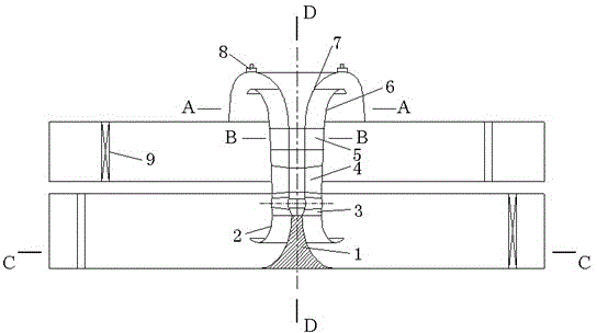
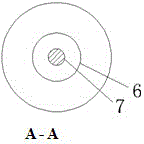
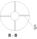
[0029]Umbrella-shaped two-way vertical pump device, consisting of two-way rectangular parallelepiped water inlet channel, rectangular parallelepiped water outlet channel, vortex elimination and anti-vortex cone 1, inlet trumpet tube 2, impeller chamber 3, guide vane body 4, racemic body 5, annular siphon water outlet Structure, rear water guide cone 7, outlet horn tube 6, hump ring shell, etc., vortex elimination and anti-vortex cone is set in the two-way cuboid water inlet flow channel under the inlet horn tube, the inlet of the impeller chamber is connected to the inlet horn tube, and the outlet of the impeller chamber is connected to the guide The leaf body, the racemic body, the rear guide water cone, and the outlet trumpet tube are sequentially arranged on the upper part of the guide vane body. The racemic body is composed of a hub, blades and a shell. The hub of the racemic body is smoothly connected with the hub of the guide vane body and the rear guide water cone respec...


PUM


Abstract

The invention belongs to the technical field of hydraulic engineering and discloses a beveled bidirectional vertical pump device which comprises a bidirectional rectangular water inlet runner, a rectangular water outlet runner, an eddy elimination and prevention cone, an inlet flared pipe, an impeller chamber, a guide vane part, a despinner, an annular siphonic water outlet structure, a rear water guide cone, an outlet flared pipe and a humped annular shell. The eddy elimination and prevention cone is arranged in the rectangular water inlet runner below the inlet flared pipe, an inlet of the impeller chamber is connected with the inlet flared pipe, and an outlet of the impeller chamber is connected with the guide vane part. The despinner, the rear water guide cone and the outlet flared pipe are sequentially arranged on the upper portion of the guide vane part, the upper annular side of the humped annular shell is smoothly connected with the upper edge of the rear water guide cone, the lower annular side of the humped annular shell is positioned in the rectangular water outlet runner to form the annular siphonic water outlet structure, and the humped tope of the annular siphonic water outlet structure is provided with a vent hole connector connected with a vacuum breaker valve. The beveled bidirectional vertical pump device is structurally reasonable and scientific, has four functions of self-discharging, self-sucking, pump-discharging and pump-sucking and is high in automation degree and convenient to operate and manage, efficiency of the pump device is improved, and investment is saved.

Description

technical field [0001] The invention relates to a hydraulic engineering facility, in particular to the structure of a bidirectional vertical pump device, and belongs to the technical field of hydraulic engineering. Background technique [0002] In order to achieve the purpose of two-way pumping for irrigation and drainage and self-drainage and self-introduction, the early projects adopted the hub layout of "one station and four gates" to achieve this purpose. In recent years, a number of large and medium-sized box-culvert bi-directional channel pump devices have been built in areas along the river and lake by using a two-way pump station water inlet and outlet device (patent number: 02286342.7), and an open water pump outlet has been applied for the water outlet structure of the pump device. Laboratory (Patent No.: 96231988.0), through pump device model tests and CFD calculations, it can be found that the flow state in the traditional box-culvert outlet channel is turbulent,...

Claims


Application Information

Patent Timeline
Patent Type & Authority Patents(China)
IPC IPC(8): F04D29/52
Inventor 刘超杨帆周济人金燕
Owner YANGZHOU UNIV
Why Eureka
Try Eureka