
Steam explosion device for plant fiber processing

A technology of steam explosion device and plant fiber, which is applied in the field of steam explosion, can solve the problem that the steam explosion device is difficult to achieve rapid blasting, and achieve the effect of improving equipment safety and operability, improving replaceability, and improving roads

Pending Publication Date: 2018-08-17
BEIJING XINRUIDE ENVIRONMENTAL PROTECTION TECH GO LTD +1
View PDF1 Cites 0 Cited by
  • Summary
  • Abstract
  • Description
  • Claims
  • Application Information

AI Technical Summary

Problems solved by technology

[0008] The purpose of the present invention is to provide a steam explosion device for plant fiber treatment, which solves the problem that the existing steam explosion device is difficult to achieve rapid blasting

Method used


Image

  • Steam explosion device for plant fiber processing

Examples


Embodiment 1

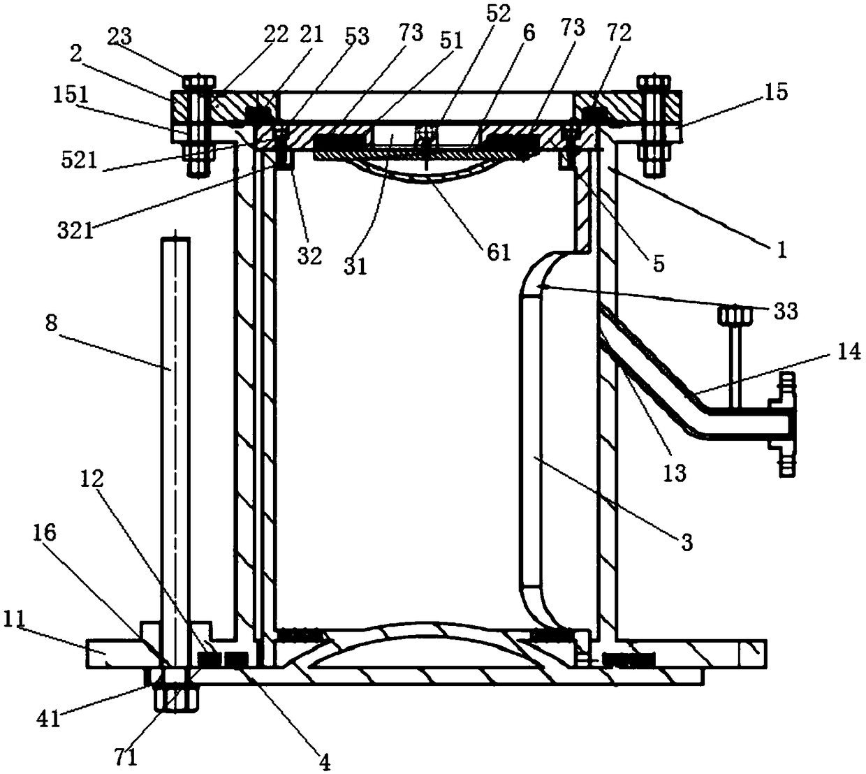
[0031] see figure 1 , a steam explosion device for plant fiber processing provided by the present invention, the steam explosion device includes: an outer warehouse 1, shaped as a tube body, placed vertically, the outer wall of the lower opening end of the outer warehouse 1 is along the outer circumferential direction of the outer warehouse An annular lower connecting portion 11 is protrudingly provided, and at least one annular first sealing groove 12 is provided along the circumferential direction of the annular lower connecting portion at both ends of the lower surface of the annular lower connecting portion 11 close to the lower opening end. An air inlet 13 is provided, and a high-temperature and high-pressure air inlet pipe 14 is inserted into the air inlet 13 to form the passage of high-temperature and high-pressure gas; an annular cover plate 2 is provided on the upper opening end of the outer warehouse 1 and connected The warehouse 1 forms a detachable connection, the ...

Embodiment 2

[0038] The outer wall of the upper opening end of the outer warehouse 1 protrudes along the outer circumference of the outer warehouse 1 with an annular upper connecting portion 15, and the two ends of the annular upper connecting portion 15 are respectively provided with an upper connecting hole 151, correspondingly, the two ends of the annular cover plate 2 are respectively An upper connection through hole 22 corresponding to the upper connection hole 151 is opened, and two fixing members 23 are inserted in the upper connection through hole 22 and the upper connection hole 151 to form a detachable connection between the annular cover plate 2 and the outer warehouse 1 . All the other are with embodiment 1.

Embodiment 3

[0040] The inner wall of the upper port of the inner chamber 3 protrudes along the horizontal direction with an annular protrusion 32, and the two ends of the upper surface of the annular protrusion 32 are respectively provided with a blind installation hole 321 along the vertical direction. Correspondingly, the two ends of the annular bottom plate 5 Mounting holes 521 matching the blind mounting holes 321 are provided respectively, and the fixing rods 53 are inserted into the mounting holes 521 and the blind mounting holes 321 to form a detachable connection between the annular bottom plate 5 and the inner compartment 3 .

[0041] Wherein, the fixing rod 53 is a bolt, and the distance is designed according to the pressure vessel design standard, and the hole distance is less than 4.5 times the diameter of the bolt. All the other are with embodiment 1.


PUM


Abstract

The invention relates to a steam explosion device for plant fiber processing. The device comprises an outer bin, an annular cover plate, an inner bin, a bottom cover, an annular bottom plate, an innercover, at least one first sealing strip, a second sealing strip and at least one third sealing strip, wherein the lower opening end of the outer bin is provided with a lower connecting part, two endsof the lower connecting part are provided with first sealing grooves, the side wall of the outer bin is provided with an air inlet hole, and a high-temperature high-pressure air inlet pipe is inserted in the air inlet hole; the annular cover plate covers an upper opening end of the outer bin, the portion, at two ends of the inner side of the upper opening end, of the annular cover plate is provided with a second sealing groove; the inner bin is inserted in the outer bin; the bottom cover covers a lower end port of the inner bin, and two ends of the upper surface of the bottom cover are provided with first sealing bulges; the annular bottom plate covers the upper end of the inner bin, two ends of the upper surface of the annular bottom plate are respectively provided with second sealing bulges, two ends of the lower surface of the annular bottom plate are provided with third sealing grooves; the inner cover covers the lower surface of the annular bottom plate, and two ends of the uppersurface of the inner cover are provided with third sealing bulges. The steam explosion device for the plant fiber processing has the advantages that it can be achieved that a plant fiber can performsteam explosion under the effect of medium-high-pressure saturated steam, so that a fiber can be separated from other substances in the plant fiber, thereby realizing the real steam explosion processing of a plant.

Description

technical field [0001] The invention belongs to the technical field of steam explosion, in particular to a steam explosion device for processing plant fibers. Background technique [0002] Steam explosion, that is, steam explosion, is a technology that uses the explosion process realized by the principle of steam catapult to pretreat biomass. [0003] The essence of its technology is: to release the steam molecules infiltrated into the plant tissue instantaneously, so that the internal energy of the steam can be converted into mechanical energy and act on the interlayer of biomass tissue cells, so that the raw materials can be decomposed according to the purpose with less energy. Because it not only avoids the secondary pollution problem of chemical treatment, but also solves the problem of low efficiency of biological treatment, it is the most promising pretreatment technology in the field of biomass conversion. [0004] The fibers in plant cells are bonded by lignin. Unde...

Claims


Application Information

Patent Timeline
IPC IPC(8): D21B1/36
CPCD21B1/36
Inventor 安健飞曹宏元曹学伟赵卫明王铁刚李如英
Owner BEIJING XINRUIDE ENVIRONMENTAL PROTECTION TECH GO LTD
Learn More