
Method for slotting anode

A technology of anode and mold core, which is applied in the field of aluminum electrolysis, can solve the problems of occupying a large space and cannot satisfy the vibration platform, and achieve the effects of saving raw materials, reducing electrolysis energy consumption, and good slotting effect

Inactive Publication Date: 2010-12-29
HUNAN CHUANGYUAN NEW MATERIALS
View PDF6 Cites 4 Cited by
  • Summary
  • Abstract
  • Description
  • Claims
  • Application Information

AI Technical Summary

Problems solved by technology

The disadvantage of this slotting method is that it cannot meet the needs of forming machines with a non-rotatable vibration platform and takes up a lot of space.

Method used


Image

  • Method for slotting anode
  • Method for slotting anode
  • Method for slotting anode

Examples


Embodiment 1

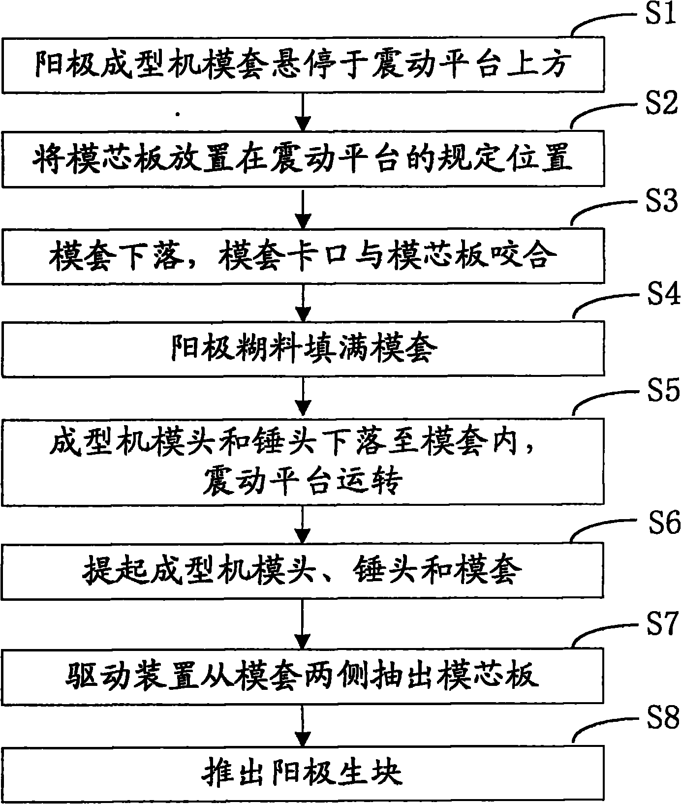
[0039] Embodiment one, see figure 1 , is the flow chart of this embodiment.

[0040] Step S1, the die set of the anode forming machine hovers above the vibrating platform.

[0041] Step S2, placing the mold core plate on the specified position of the vibrating platform.

[0042] When placing the core plate, auxiliary tools can be used to fix it, for example, the position can be marked on the vibration platform, or the driving device can be set in advance, and the core plate can be controlled by the driving device.

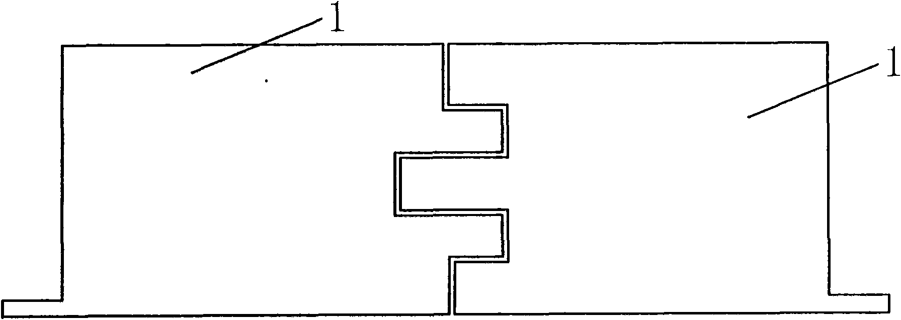
[0043] see figure 2 , The core plate 1 is composed of two left and right pieces to facilitate the extraction of the core plate after the anode green block is formed. The left and right mold core panels are airtight and seamless to ensure the strength of the mold core panels; the left and right parts can be connected by a fixing device, or fixed to each other by shape fit. figure 2 What is shown in is only an example, and the joints of the left and right core ...

Embodiment 2

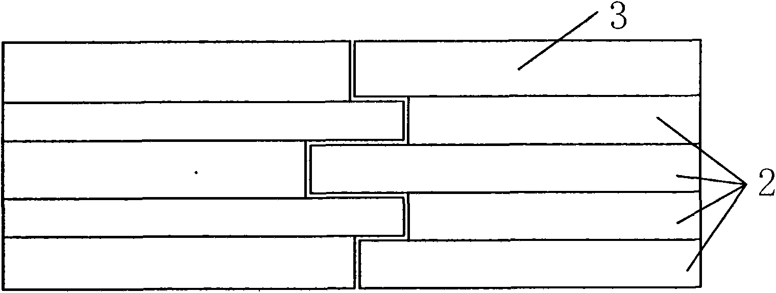
[0070] The steps are roughly the same as the above-mentioned first embodiment, the difference is that the mold core plate is composed of upper and lower parts.

[0071] The upper and lower parts of the core plate are airtight and seamless to ensure the strength of the core plate; it can be connected by a fixing device, which can be a structure similar to a C-type pin, and the two ends of the C-type pin are respectively inserted into the core plate upper and lower parts. Alternatively, the joint between the upper and lower parts of the mold core plate is a shape that facilitates the extraction of the lower half of the mold core plate.

[0072] see Figure 9 and Figure 10 , when pulling out the core plate from the anode green block, first pull out the lower part of the core plate (that is, the covering strip 2) from one side of the mold casing, and let the upper part of the core plate (that is, the first covering strip 3) fall naturally into the position of the original lowe...


PUM


Abstract

The invention discloses a method for slotting an anode in the electrolytic aluminum industry. The technical scheme is that: the method comprises the following steps of: placing a die core plate consisting of a left part and a right part in an anode molding die sleeve; and after the anode is made into a block and molded, pulling the die core plate out from the two sides of the die sleeve by using a drive device. The slotting method has good effect, namely, irregularly-shaped slots of which middle parts are lower than tops at two ends can be reserved, and compared with straight slots, are more favorable for driving CO2 foams to quickly leave the bottom of the anode; and the slotting method also has the advantages of simple process, convenient use and raw material saving.

Description

technical field [0001] The invention relates to the field of aluminum electrolysis, in particular to a method for slotting an anode. Background technique [0002] When using the prebaked anode carbon block with grooves at the bottom, the surrounding electrolyte flow field is calculated, and it is found that part of the gas can be discharged outwards through the bottom groove, which reduces the residence time of the bubbles at the bottom of the anode carbon block and the air bubble coverage at the bottom of the anode carbon block rate, which is conducive to reducing the overvoltage (or membrane voltage) of the anode carbon block and the effect coefficient of the anode carbon block, reducing the energy consumption of electrolysis; on the other hand, the gas drives the electrolyte into the exhaust ditch, and then enters the side channel of the electrolytic cell, expanding the The electrolyte circulation channel promotes the flow of electrolyte around the anode carbon block and ...

Claims


Application Information

Patent Timeline
Patent Type & Authority Applications(China)
IPC IPC(8): B28B7/00B28B1/08C25C3/12
Inventor 高小明龚克成
Owner HUNAN CHUANGYUAN NEW MATERIALS
Learn More