Eureka AIR delivers breakthrough ideas for toughest innovation challenges, trusted by R&D personnel around the world.

Cast-in-place prestressed concrete sandwiched composite beamless floor slab structure

A beamless floor slab and concrete technology, which is applied in the direction of floor slabs, building components, building structures, etc., can solve problems such as steel bar erosion, achieve the effects of reducing project cost, easy handling, and shortening the construction period

Inactive Publication Date: 2022-01-18
QINGDAO XINHUAYOU CONSTR GROUP
View PDF14 Cites 0 Cited by
  • Summary
  • Abstract
  • Description
  • Claims
  • Application Information

AI Technical Summary

Problems solved by technology

The bigger problem with the prestressed cast-in-place concrete hollow slab structure that has emerged in recent years is that a large number of hollow pipes are placed inside this structure. During the construction of cast-in-place concrete, a certain amount of water will remain, which will remain inside the slab. The accumulated water will corrode the steel bars in the slab over time

Method used


Image

  • Cast-in-place prestressed concrete sandwiched composite beamless floor slab structure
  • Cast-in-place prestressed concrete sandwiched composite beamless floor slab structure
  • Cast-in-place prestressed concrete sandwiched composite beamless floor slab structure

Examples


Embodiment 1

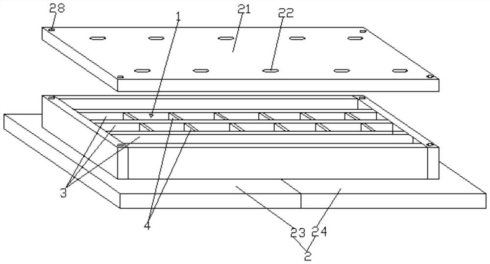
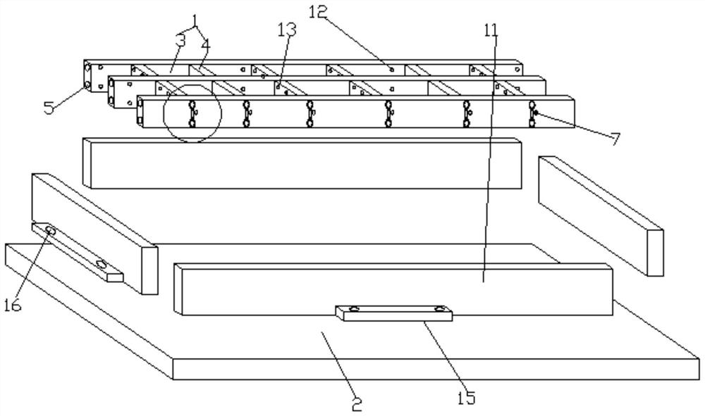
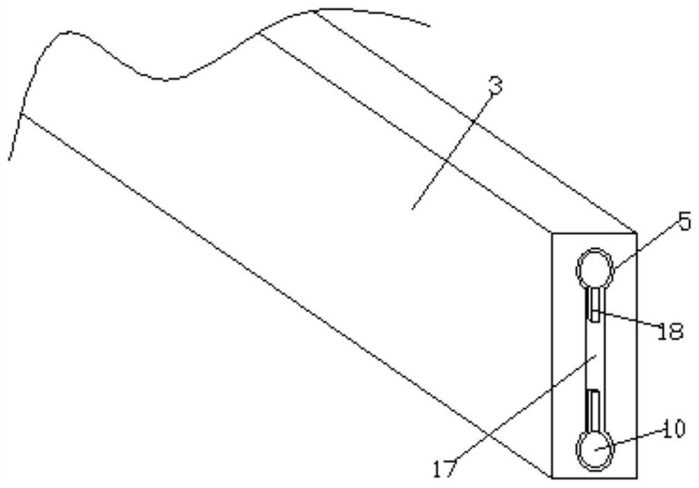
[0033] see Figure 1-6 , according to an embodiment of the present invention, a cast-in-situ prestressed concrete sandwich composite beamless floor structure includes a beamless floor body 1 and a bottom formwork 2, the bottom formwork 2 is arranged at the bottom of the beamless floor body 1, and the The beamless floor body 1 includes several transverse partition panels 3, and the adjacent transverse partition panels 3 are fixedly connected by several reinforcing panels 4, and the interior of the transverse partition panels 3 and the reinforcing panels 4 Both are cavity structures, the transverse partition plate 3 is provided with a transverse reinforcement hole 5, and the common connection between the reinforcement plate 4 and the transverse partition plate 3 is provided with a vertical reinforcement hole 6 and a pipeline hole 7, so A line pipe 8 is arranged in the pipeline hole 7, a vertical steel bar 9 is arranged in the vertical steel bar hole 6, a horizontal steel bar 10 ...

Embodiment 2

[0035] see Figure 1-4, the number is four on the outer wall of the surrounding board 11 is fixed with a mounting plate 15, the mounting plate 15 is provided with a threaded hole 16, each of the lateral partitions 3 provided with the lateral The number of reinforcing bar holes 5 is two, and connecting grooves 17 are arranged between the transverse reinforcing bar holes 5 on each of the transverse dividing plates 3, and the connecting grooves 17 communicate with the outside, and the transverse reinforcing bars 10 Inserted into the horizontal steel bar hole 5, and the corresponding side of the horizontal steel bar 10 is evenly distributed with in-line reinforcing ribs 18, and the vertical steel bar holes provided on each of the reinforcing plates 4 The number of 6 is two, and a secondary connection groove 19 is provided between the vertical reinforcement holes 6 on each of the reinforcing plates 4, and the secondary connection groove 19 communicates with the outside, and the ver...

Embodiment 3

[0038] see Figure 1-5 , the pillars 14 pass through the bottom formwork 2 and the beamless floor body 1 together, the bottom formwork 2 is divided into a left formwork 23 and a right formwork 24, and the junction of the left formwork 23 and the right formwork 24 Both are provided with a half-through slot, and the two half-through slots are merged into a full-through slot. The pillar 14 passes through the full-through slot. The sound insulation mechanism includes a sound insulation board 25, the bottom of the sound insulation board 25, the The beamless floor body 1 is fixed with a corresponding corresponding plate 26, and the corresponding plate 26 and the pillar 14 are provided with several corresponding openings, and steel bars are provided in the openings. The interior of the sound insulation board 25 is filled with sound insulation cotton, and several leak grooves are evenly distributed on the sound insulation board 25, and the secondary penetration opening 27 for the pill...


PUM


Abstract

The invention discloses a cast-in-place prestressed concrete sandwiched composite beamless floor slab structure which comprises a beamless floor slab body and a bottom formwork, wherein the bottom formwork is arranged at the bottom of the beamless floor slab body, the beamless floor slab body comprises a plurality of transverse partition plates, the adjacent transverse partition plates are fixedly connected through a plurality of reinforcing plates, the interiors of the transverse partition plates and the reinforcing plates are of a cavity structure, transverse steel bar holes are formed in the transverse partition plates, and vertical steel bar holes and pipeline holes are formed in the joints of the reinforcing plates and the transverse partition plates. The cast-in-place prestressed cast-in-place concrete sandwiched composite beamless floor slab structure and a construction method have the beneficial effects that the problem that the existing cast-in-place concrete beamless floor slab cannot completely meet the building requirements, especially the problems of sound insulation, heat preservation and corrosion of steel bars, which cannot be solved, can be solved, the construction period can be shortened, and the construction cost can be reduced; and the structure can be used for beamless floor slab structure systems of various industrial and civil buildings such as multi-layer, high-rise and super high-rise buildings.

Description

technical field [0001] The invention relates to the field of construction, in particular to an in-situ prestressed concrete sandwich composite beamless floor structure. Background technique [0002] At present, the prestressed or non-prestressed cast-in-place concrete beamless floor slab structure adopted by the known traditional construction methods has a large thickness and self-weight, high cost, and is limited by the span of the slab, so it is difficult to popularize. In recent years, prestressed cast-in-place concrete hollow slab structures have emerged. Since the pipes used to form the hollow in the plate can only be arranged in one direction, the internal force distribution of the plate in the vertical and horizontal directions is quite different. The direction along the pipe is the main force direction, and the direction perpendicular to the pipe is the secondary force direction. Due to the one-way stress plate, the thickness of the plate is increased, and the reinf...

Claims


Application Information

Patent Timeline
IPC IPC(8): E04B5/32E04B5/48E04B1/86
CPCE04B5/32E04B5/48E04B1/86
Inventor 郗猛高原李堂飞
Owner QINGDAO XINHUAYOU CONSTR GROUP
Why Eureka
Eureka Blog
Learn More