Supercharge Your Innovation With Domain-Expert AI Agents!

Valve oil seal with adjustable leakage rate

A valve oil seal, adjustable technology, applied in the direction of lift valve, engine components, machine/engine, etc., can solve the problems of inability to carry out leakage, short service life, increased working temperature, etc., to achieve long service life and strong practicability , maintain the effect of lubrication

Pending Publication Date: 2022-01-18
烟台坤正密封制品有限公司
View PDF0 Cites 0 Cited by
  • Summary
  • Abstract
  • Description
  • Claims
  • Application Information

AI Technical Summary

Problems solved by technology

[0004] The purpose of the present invention is to provide a valve oil seal to solve the problem that the leakage of the existing adjustable valve oil seal proposed in the above background technology is controlled by the self-tightening spring during use, and the working temperature increases. , resulting in a decrease in the radial force, resulting in the failure of the sealing lip. In order to compensate for the decrease in the radial force caused by the temperature rise, the general valve oil seal tightens the radial force at room temperature, which in turn leads to an increase in friction at room temperature, and the single The sealing lip is extremely vulnerable to a large amount of wear and "outgassing" under high temperature and high pressure, resulting in the inability to adjust the leakage and short service life

Method used


Image

  • Valve oil seal with adjustable leakage rate
  • Valve oil seal with adjustable leakage rate
  • Valve oil seal with adjustable leakage rate

Examples


Embodiment Construction

[0020] The following will clearly and completely describe the technical solutions in the embodiments of the present invention with reference to the accompanying drawings in the embodiments of the present invention. Obviously, the described embodiments are only some, not all, embodiments of the present invention. Based on the embodiments of the present invention, all other embodiments obtained by persons of ordinary skill in the art without making creative efforts belong to the protection scope of the present invention.

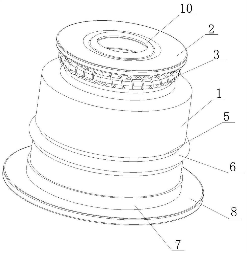
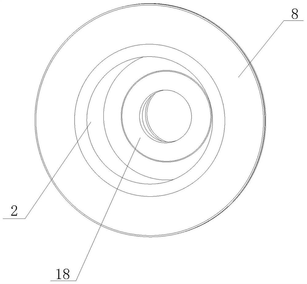
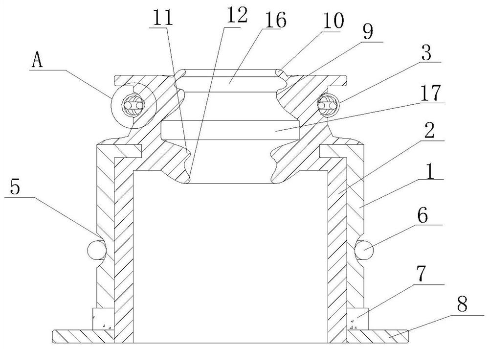
[0021] see Figure 1-4 , the present invention provides a technical solution: a valve oil seal with adjustable leakage, including a reinforced frame 1, the inner wall of the reinforced frame 1 is fixedly connected with a rubber body 2, and the outer wall of the rubber body 2 is provided with a first spring near the top of the reinforced frame 1 Groove 4, the inner wall of the first spring groove 4 is provided with a self-locking spring structure 3, the outer w...


PUM


Abstract

The invention discloses a valve oil seal with adjustable leakage rate. The valve oil seal comprises a reinforcing framework, wherein a rubber body is fixedly connected to the inner wall of the reinforcing framework; a first spring groove is formed in the position, close to the top of the reinforcing framework, of the outer wall of the rubber body; a self-locking spring structure is arranged on the inner wall of the first spring groove; the outer wall of the self-locking spring structure is connected with the inner wall of the first spring groove in a sleeved mode and is in close fit with the inner wall of the first spring groove; a main sealing lip is arranged on the inner wall, close to the self-locking spring structure, of the rubber body; a protection structure is arranged at the bottom, close to the main sealing lip, of the inner wall of the rubber body; an adjusting ring is fixedly connected to the bottom of the reinforcing framework; the bottom of the adjusting ring is fixedly connected with a fixing ring; and a second spring groove is formed in the position, close to the top of the adjusting ring, of the outer wall of the reinforcing framework. According to the valve oil seal with adjustable leakage rate, the stress of the reinforcing framework is adjusted by replacing an adjusting spring, so that the adjusting ring is slightly deformed, the fit clearance at the main sealing lip can be changed, interference fit is generated at the main sealing lip, and the effect of adjusting the leakage rate is achieved.

Description

technical field [0001] The invention belongs to the technical field of auto parts, and in particular relates to a valve oil seal with adjustable leakage. Background technique [0002] The valve oil seal and the valve guide are connected together and installed on the cover of the automobile engine. The function is to prevent the oil from flowing into the internal combustion tank of the engine, causing leakage and penetration of the oil loss. The valve oil seal is one of the common seals of the engine. The structure is generally composed of the vulcanization of the outer skeleton and the fluorine rubber, and a self-tightening spring or a steel wire is installed in the bore to realize the sealing of the valve guide rod on the engine. [0003] The leakage of the traditional valve oil seal is controlled by the self-tightening spring, which cannot be adjusted, and when the valve oil seal is used, the radial force decreases due to the increase of the working temperature, so that th...

Claims


Application Information

Patent Timeline
IPC IPC(8): F01L3/08
CPCF01L3/08
Inventor 鲁爱强于志成
Owner 烟台坤正密封制品有限公司
Features
  • R&D
  • Intellectual Property
  • Life Sciences
  • Materials
  • Tech Scout
  • Unparalleled Data Quality
  • Higher Quality Content
  • 60% Fewer Hallucinations
Learn More