
Non-reciprocal optical adjustable phase bias modulator

A phase-biased, non-reciprocal technology, used in lasers, laser parts, phonon exciters, etc., can solve the problem of inability to achieve continuous precision adjustment, achieve accurate microwave-optical phase detection, increase repetition frequency, portable The effect of efficient control means

Active Publication Date: 2022-01-18
XIAN INSTITUE OF SPACE RADIO TECH
View PDF8 Cites 0 Cited by
  • Summary
  • Abstract
  • Description
  • Claims
  • Application Information

AI Technical Summary

Problems solved by technology

The above phase shift structures are all Faraday rotators and birefringent crystal wave plates, which introduce a specific initial phase shift difference for bidirectionally transmitted light The size depends on the material, combination and thickness of the wave plate, so the phase shifter can only provide a fixed and discrete phase offset value, but cannot achieve continuous precision adjustment and provide tuning margin. This is a non-reciprocal phase shifter in various applications In-depth research and innovative optimization of scenarios have certain limitations

Method used


Image

  • Non-reciprocal optical adjustable phase bias modulator
  • Non-reciprocal optical adjustable phase bias modulator
  • Non-reciprocal optical adjustable phase bias modulator

Examples


Embodiment Construction

[0029] Exemplary embodiments of the present disclosure will be described in more detail below with reference to the accompanying drawings. Although exemplary embodiments of the present disclosure are shown in the drawings, it should be understood that the present disclosure may be embodied in various forms and should not be limited by the embodiments set forth herein. Rather, these embodiments are provided for more thorough understanding of the present disclosure and to fully convey the scope of the present disclosure to those skilled in the art. It should be noted that, in the case of no conflict, the embodiments of the present invention and the features in the embodiments can be combined with each other. The present invention will be described in detail below with reference to the accompanying drawings and examples.

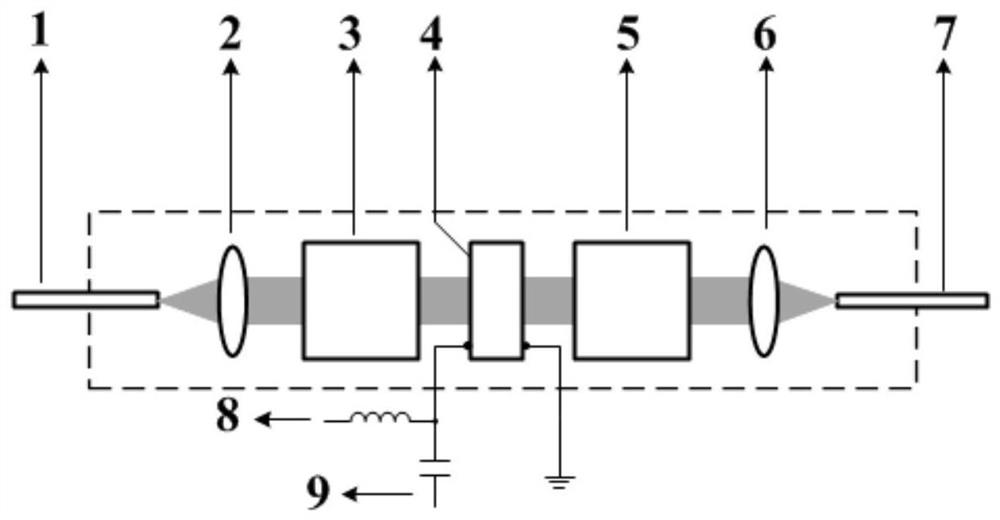
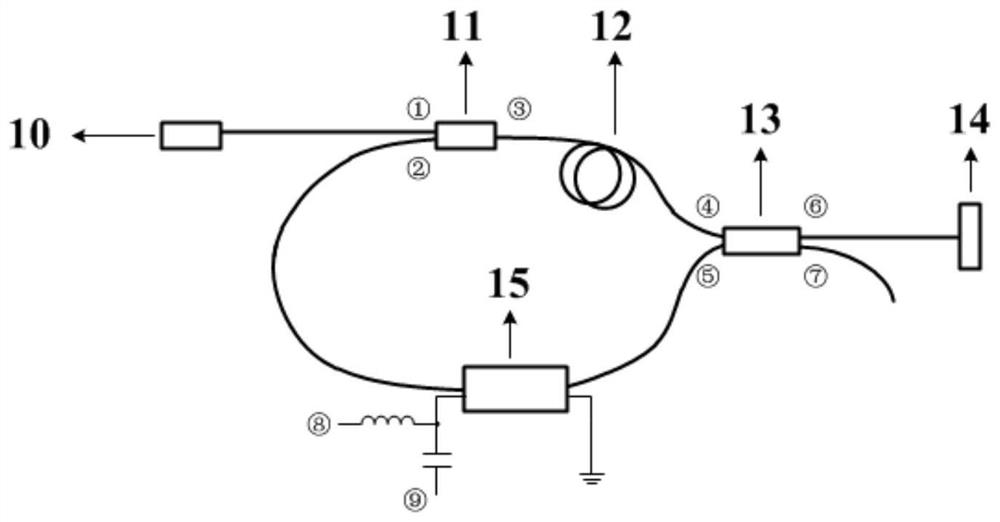
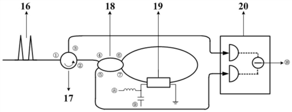
[0030] figure 1 It is a schematic diagram of a non-reciprocal optically adjustable phase bias and modulator of the present invention. Such as figure 1 As s...


PUM


Abstract

The invention discloses a non-reciprocal optical adjustable phase bias modulator, which comprises a first polarization maintaining optical fiber, a first collimating lens, a first Faraday rotator, a linear electro-optical modulation crystal, a second Faraday rotator, a second collimating lens, a second polarization maintaining optical fiber, a DC input end and an RF input end. According to the invention, the free tuning of the optical non-reciprocal phase bias is realized by utilizing the electro-optical modulation characteristic of the electro-optical crystal, and the phase modulation function can be realized according to application requirements.

Description

technical field [0001] The invention belongs to the field of fiber laser technology, in particular to a non-reciprocal optical adjustable phase bias modulator. Background technique [0002] Since the 1990s, ultrafast laser technology has attracted the attention of various countries, and ultrafast fiber lasers have become a research hotspot in the field of ultrafast. With the rapid development of technology, femtosecond fiber laser has been widely used in precision measurement, ophthalmology, medical imaging, micro-processing and other fields, and has become the preferred seed light source for various optical systems. [0003] In practical applications, it is of great significance to study fully deflection-maintaining femtosecond fiber lasers and further improve their performance. Traditional passive mode-locking methods include saturable absorber (SA), nonlinear polarization rotation mode-locking (NPR) and nonlinear amplifying loop mirror (NALM). Among them, the NALM fiber...

Claims


Application Information

Patent Timeline
Patent Type & Authority Applications(China)
IPC IPC(8): H01S3/067H01S3/094
CPCH01S3/094042H01S3/06712H01S3/06754Y02D30/70
Inventor 赵春勃姚嘉丽汪会波拓卓越杜二旺蒙艳松
Owner XIAN INSTITUE OF SPACE RADIO TECH
Learn More