
Angle-adjustable printing screen and printing device

A screen and angle technology, applied in printing, printing presses, rotary printing presses, etc., can solve the problems of large adjustment error and reduce the printing quality of cells, and achieve the effect of improving the accuracy of angle adjustment

Inactive Publication Date: 2022-01-21
无锡奥特维旭睿科技有限公司
View PDF7 Cites 0 Cited by
  • Summary
  • Abstract
  • Description
  • Claims
  • Application Information

AI Technical Summary

Problems solved by technology

The traditional center rotation adjustment method has the disadvantage of large adjustment error, which reduces the printing quality of the cell

Method used


Image

  • Angle-adjustable printing screen and printing device
  • Angle-adjustable printing screen and printing device
  • Angle-adjustable printing screen and printing device

Examples


no. 1 example

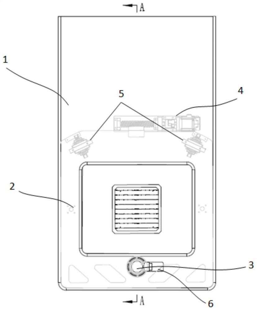
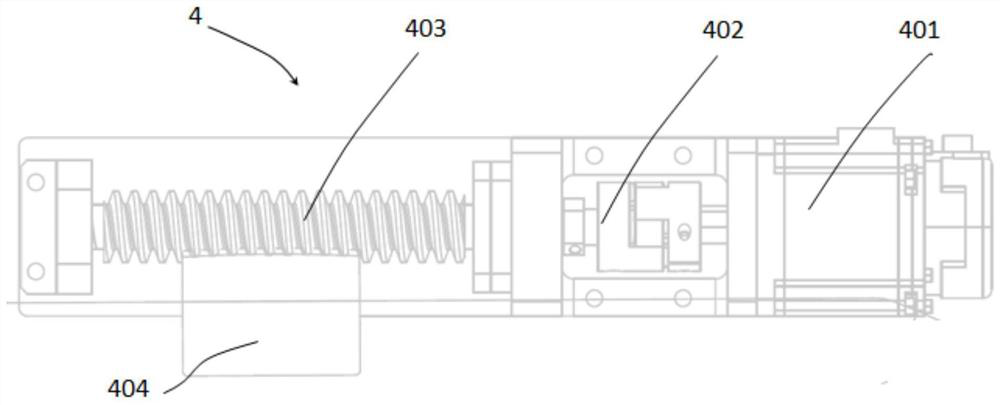
[0056] Such as figure 1As shown, the angle-adjustable printing screen provided by this embodiment includes a substrate 1, a screen assembly 2, a main shaft 3, a driving mechanism 4 and a supporting mechanism 5, wherein: the first end of the screen assembly 2 is rotatably connected to the main shaft 3 on substrate 1. The driving mechanism 4 is arranged on the substrate 1, and the driving mechanism 4 is connected to the second end of the screen assembly 2 opposite to the first end, and the driving mechanism 4 is used to drive the screen assembly 2 to rotate. The supporting mechanism 5 is arranged on the substrate 1 , and the second end of the screen assembly 2 is slidably supported on the supporting mechanism 5 .

[0057] It can be seen that the main shaft 3 as a rotating component is connected to the first end of the screen assembly 2 , and the driving mechanism 4 drives the screen assembly 2 to rotate eccentrically around the main shaft 3 , thereby realizing the angle adjustm...

no. 2 example

[0064] The structure and working principle of the angle-adjustable printing screen provided by the second embodiment of the present invention are basically the same as those of the angle-adjustable printing screen in the above-mentioned first embodiment. For the rest of the same technical points, please refer to the relevant description of the above-mentioned first embodiment.

[0065] Figure 7 for Figure 6 Enlarged view of the driving mechanism 4 in, such as Figure 7 As shown, the driving mechanism 4 in this embodiment includes a second servo motor 405 , a second coupling 406 , a screw 407 , a screw nut 408 , a first crossed roller bearing 409 and a sliding rail mechanism 410 .

[0066] Wherein: the second servo motor 405 is connected on the base plate 1 , the screw rod 407 is connected to the driving end of the second servo motor 405 through the second coupling 406 , and the screw nut 408 is screwed on the screw rod 407 . The outer ring body of the first crossed roller...


PUM


Abstract

The invention provides an angle-adjustable printing screen which comprises a base plate, a screen assembly, a main shaft, a driving mechanism and a supporting mechanism; wherein the first end of the screen assembly is rotationally connected to the base plate through the main shaft; the driving mechanism is arranged on the base plate, the driving mechanism is connected with the second end, opposite to the first end, of the screen assembly, and the driving mechanism is used for driving the screen assembly to rotate; the supporting mechanism is arranged on the base plate, and the second end of the screen assembly is supported on the supporting mechanism in a sliding mode. Through cooperation of the main shaft, the driving mechanism and the supporting mechanism, according to the angle-adjustable printing screen provided by the invention, the screen assembly eccentrically rotates around the main shaft to realize angle adjustment, so that the angle adjustment precision is improved.

Description

technical field [0001] The invention relates to the field of battery production, in particular to an angle-adjustable printing screen and a printing device. Background technique [0002] In the production process of solar cell modules, one link is to print electrodes on the cell sheet, and the screen printing process is generally used at this stage. During the feeding process, the cells will be angularly offset from the workbench. Therefore, it is necessary to adjust the angle of the screen assembly to meet the screen printing requirements of the cell. [0003] In the traditional technology, in order to adjust the angle of the screen assembly, the center of the screen assembly is rotated and assembled on the substrate through a rotating mechanism, and the screen assembly is driven to rotate around the rotating mechanism by a driving mechanism to achieve angle adjustment. The traditional center rotation adjustment method has the disadvantage of large adjustment error, which...

Claims


Application Information

Patent Timeline
Patent Type & Authority Applications(China)
IPC IPC(8): B41F15/08B41F15/34B41F15/42H01L31/0224H01L31/18
CPCB41F15/34B41F15/42B41F15/08H01L31/022425H01L31/18Y02P70/50
Inventor 殷庆辉陈兵高阳郭健徐英乾
Owner 无锡奥特维旭睿科技有限公司
Learn More