
Antiskid angle gauge

A technology of angle meter and guide slide rail, which is applied in the direction of instruments, measuring inclination, transmission devices, etc., can solve the problems of poor angle accuracy, insufficient support of test platform, and reduce the accuracy of detection, etc., to achieve high accuracy of angle adjustment , stable angle and high angle accuracy

Active Publication Date: 2022-05-13
BELIKE CHEM
View PDF9 Cites 0 Cited by
  • Summary
  • Abstract
  • Description
  • Claims
  • Application Information

AI Technical Summary

Problems solved by technology

[0004]However, most of the manufacturers of finished paper boxes and varnishes for printing proofs currently use relatively simple self-made anti-skid angle gauges, and the angle is manually adjusted. It is assisted by an angle meter. This method has disadvantages such as poor angle accuracy and insufficient support of the test platform. At the same time, it cannot detect multiple groups of paper, which reduces the accuracy of detection. Therefore, a non-slip angle meter is needed to solve the above problems. the question raised

Method used


Image

  • Antiskid angle gauge
  • Antiskid angle gauge
  • Antiskid angle gauge

Examples


Embodiment 1

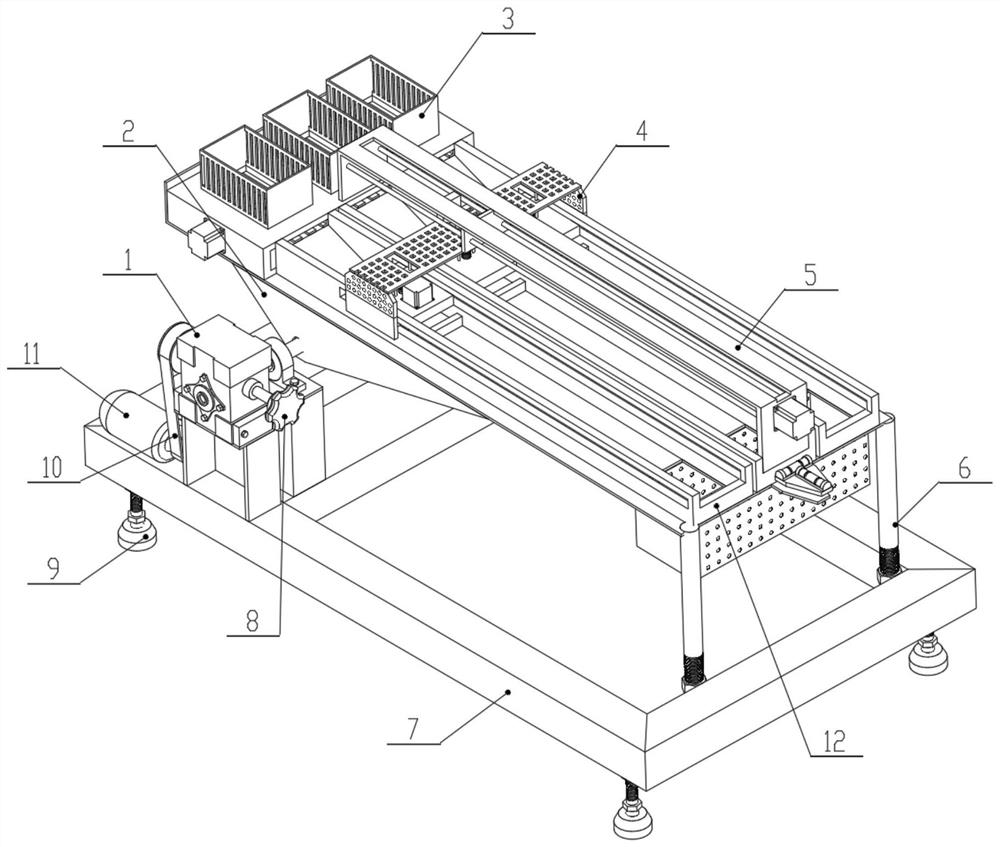
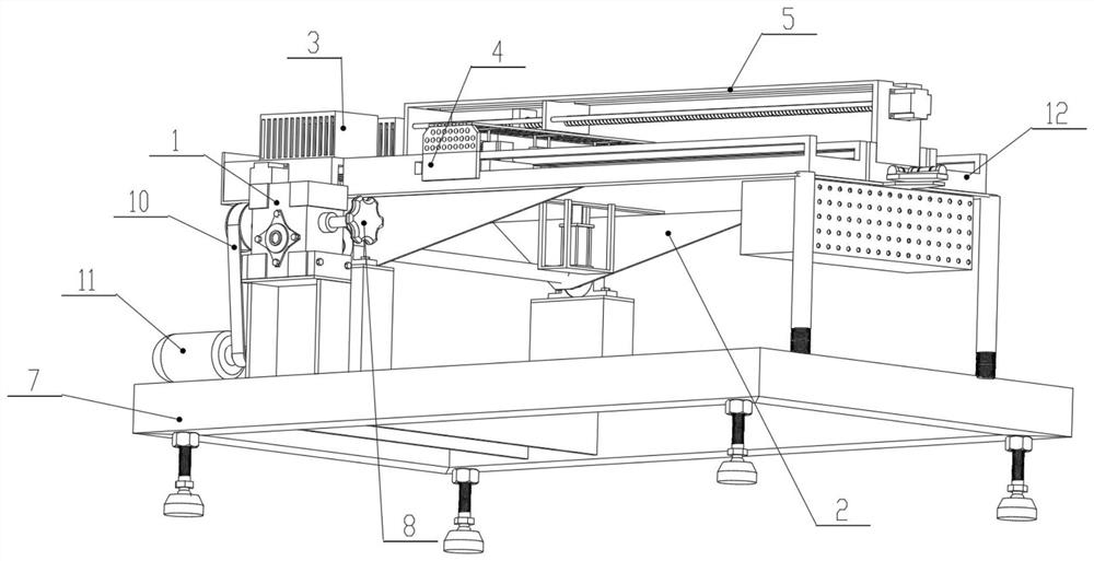
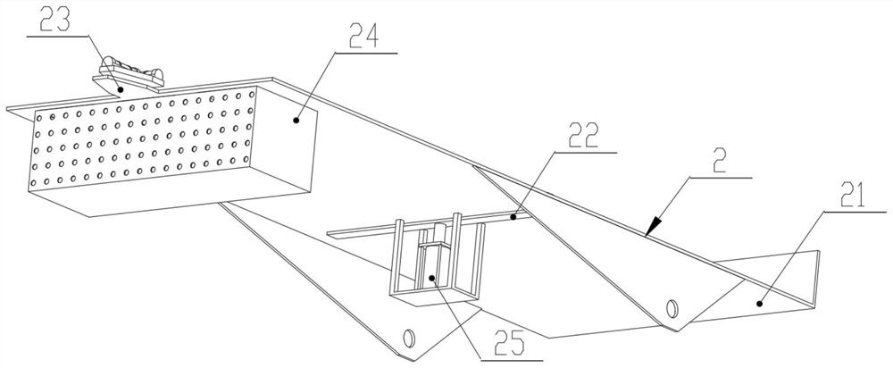
[0048] see figure 1 , image 3 , Figure 5 and Figure 6 , an embodiment provided by the present invention: an anti-slip angle meter, including a worm gear reducer 1, a supporting device 2, a paper feeding device 3, a limiting device 4, a guiding device 5, a connecting screw 6, and a supporting chassis 7 , hand wheel 8, support feet 9, connecting belt 10, servo motor 11 and guide rail 12;

[0049] The four corners of the lower end surface of the support chassis 7 are fixedly equipped with support feet 9 for supporting, and the upper end surface of the support chassis 7 is fixedly installed with a worm gear reducer 1 near the front end. A servo motor 11 is fixedly installed on the front end near the bottom, and the servo motor 11 is meshed with the worm gear reducer 1 through the connecting belt 10. The rear end face of the worm gear reducer 1 is fixedly equipped with a hand wheel 8 and an electronic angle meter. And the side end surface of the worm gear reducer 1 is provid...

Embodiment 2

[0070] On the basis of Example 1, such as Figure 10 As shown, the pushing guide plate 53 includes a supporting spring 531, a baffle plate 532 and a sliding plate 533, and the inner end surface of the sliding plate 533 is fixedly equipped with three groups of supporting springs 531 evenly and equidistantly, and the side ends of the three groups of supporting springs 531 are fixedly connected with Baffle plate 532 .

[0071] During the implementation of this embodiment, when detecting samples of different lengths to be detected, the support motor 51 can drive the sliding plate 533 to move to the front or rear accurately through the limit of the connection screw 54 and the guide slider 55 , to facilitate the positioning of the follow-up threaded slide shaft 46 to the upper center of the sample to be detected, while the support spring 531 and the baffle plate 532 can effectively improve the protection of the limiting device 4 through the action of elastic force, and improve the s...


PUM


Abstract

The invention relates to the technical field of detection equipment, in particular to an anti-skid angle gauge which comprises a turbine worm speed reducer, a supporting device, a paper conveying device, a limiting device, a guiding device, a connecting screw rod, a supporting bottom frame, a hand wheel, supporting bottom feet, a connecting belt, a servo motor and a guiding sliding rail. Supporting bottom feet used for supporting are fixedly installed at the four corners of the lower end face of the supporting bottom frame, a turbine worm speed reducer is fixedly installed at the position, close to the front end, of the upper end face of the supporting bottom frame, and a servo motor is fixedly installed at the position, close to the bottom, of the front end face of the supporting bottom frame. According to the invention, the characteristics of large reduction ratio and self-locking of the turbine worm speed reducer are utilized to realize the matching of the small low-power servo motor, the angle adjustment precision is high, and the angle of the test workbench is stable.

Description

technical field [0001] The invention relates to the technical field of detection equipment, in particular to an anti-skid angle meter. Background technique [0002] The anti-slip angle meter is a kind of printing sample used to test the printing sample, usually paper printing products or finished cartons. During the production process of printing samples and finished cartons, a layer of varnish is coated on the surface to increase the surface gloss of the product. , smoothness and waterproof performance, but after the printing samples and finished cartons are produced, the finished products will be stacked and stored in high stacks. In order to make it difficult to slip due to inclination during transportation, a requirement for an anti-skid angle is put forward for this product , to facilitate the subsequent stable transportation of printed products. [0003] For example, the patent number is: CN202021888447.4 disclosed invention patent, the utility model discloses an auto...

Claims


Application Information

Patent Timeline
Patent Type & Authority Applications(China)
IPC IPC(8): G01N19/02G01N19/04G01C9/02F16H1/16
CPCG01N19/02G01N19/04G01C9/02F16H1/16
Inventor 吴耿斌余佳轩柯海峰莫启垣崔崇江
Owner BELIKE CHEM
Learn More