Fuel guide pipe installation evaluation method under wing deformation condition

A deformation and fuel technology, which is applied to aircraft power units, aircraft parts, ground units, etc., to reduce excessive loads and fuel leakage failures, and to achieve reliable design.

Pending Publication Date: 2022-01-21
XIAN AIRCRAFT DESIGN INST OF AVIATION IND OF CHINA
View PDF0 Cites 0 Cited by
  • Summary
  • Abstract
  • Description
  • Claims
  • Application Information

AI Technical Summary

Problems solved by technology

[0005] The purpose of this application is to provide a method for evaluating the installation of fuel conduits in the case of wing deformation to solve or alleviate at least one of the problems in the background art

Method used


Image

  • Fuel guide pipe installation evaluation method under wing deformation condition
  • Fuel guide pipe installation evaluation method under wing deformation condition
  • Fuel guide pipe installation evaluation method under wing deformation condition

Examples


Embodiment Construction

[0032] In order to make the purpose, technical solution and advantages of the application more clear, the technical solution in the embodiment of the application will be described in more detail below in conjunction with the drawings in the embodiment of the application.

[0033] In order to improve the safety of the fuel pipeline, this application provides an evaluation method for the installation of the fuel pipeline under the condition of wing deformation, which realizes the evaluation and judgment of the installation layout of the fuel pipeline, and reduces the transmission of structural deformation caused by the unreasonable layout of the fuel pipeline. Excessive loads on the pipeline and fuel leakage failures make the aircraft fuel pipeline design more reliable.

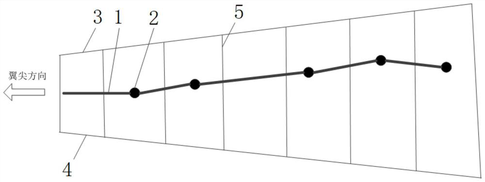
[0034] Such as figure 2 Shown is a schematic diagram of the installation structure of fuel conduits in a typical aircraft wing fuel tank. The wing fuel tank includes structures such as front beam 3, rear beam ...


PUM


Abstract

The invention provides a fuel guide pipe installation evaluation method under the wing deformation condition. The fuel guide pipe installation evaluation method comprises the steps of obtaining deformation data of a wing fuel tank inner rib plate under a typical working condition; determining the axes of all fuel guide pipes in the wing fuel tank; determining an axis included angle and an axis end spacing between adjacent fuel guide pipes according to the axes of the fuel guide pipes; selecting a fixed point on each fuel guide pipe; sequentially acquiring the displacement variation of the fixed point of each fuel guide pipe along the coordinate system of the aircraft; determining the axis of the moved fuel guide pipe according to the displacement variable quantity; and carrying out judging according to the axis included angle and the axis end spacing of all the adjacent fuel guide pipes after movement and the axis included angle and the axis end spacing of the adjacent fuel guide pipes before movement, if any one of the variable quantity of the included angle and the variable quantity of the axis end spacing exceeds a preset value, determining that the fuel guide pipes are unqualified in installation, and otherwise, determining that the fuel guide pipes are qualified in installation.

Description

technical field [0001] The application belongs to the technical field of aircraft fuel tank design, and in particular relates to a method for evaluating the installation of fuel conduits under the condition of wing deformation. Background technique [0002] The fuel delivery from the fuel pump to the power unit or the finished accessories of the fuel system is usually realized through the fuel pipeline. Due to installation and maintenance requirements and aircraft deformation that may be caused by external loads, fuel pipelines are generally installed in sections. [0003] In order to adapt to the structural deformation of the aircraft, flexible joints are usually used to connect the fuel pipes. Such as figure 1 Shown is a schematic diagram of a typical flexible joint structure. The ends of the two fuel conduits 1 are provided with sealing grooves, and sealing rings 21 are provided in the sealing grooves. For connection, an outer sleeve 23 is provided on the outside of th...

Claims


Application Information

Patent Timeline
Patent Type & Authority Applications(China)
IPC IPC(8): B64F5/00B64D37/00
CPCB64F5/00B64D37/005
Inventor 马少璞林厚焰何明
Owner XIAN AIRCRAFT DESIGN INST OF AVIATION IND OF CHINA
Why Eureka
Try Eureka