Automatic clamping device with anti-static performance for machining

A mechanical processing and clamping device technology, applied in conveyor control devices, static electricity, conveyors, etc., can solve the problems of insufficient clamping stability and inconvenient supporting use, etc., to achieve the effect of convenient processing or detection and a wide range of applications

Pending Publication Date: 2022-01-21
重庆数智源智能装备科技有限公司
0 Cites 0 Cited by

AI-Extracted Technical Summary

Problems solved by technology

[0004] The object of the present invention is to provide an automatic clamping device with antistatic performance for mechanical processing, so as to solve the problem that the existing automatic clamping device for mechanical processing proposed in the above-mentioned bac...

Method used

Feeding clamping mechanism 15 includes connecting plate 1501, rotating shaft 1502, rotating plate 1503, clamping frame 1504, side plate 1505, the second miniature expansion rod 1506 and the second clamping plate 1507, below the mounting plate 14 The connecting plate 1501 is fixed, and the lower side of the connecting plate 1501 is installed with the rotating plate 1503 through the rotating shaft 1502, the clamping frame 1504 is fixed under the rotating plate 1503, and the side plates 1505 are fixed on both sides below the clamping frame 1504 , the inner side of the side plate 1505 is installed with the second micro telescopic rod 1506, and the top of the second micro telescopic rod 1506 is fixed with the second clamping plate 1507, the rotating plate 1503 and the clamping frame 1504 pass between the rotating shaft 1502 and the connecting plate 1501 A rotating structure is formed between them, and a second micro-telescopic rod 1506 and a second clamping plate 1507 are installed symmetrically on both sides inside the rotating plate 1503, and the position of the second clamping plate 1507 is conveniently telescopically adjusted by the second micro-telescopic rod 1506, so that Two groups of symmetrically arranged arc-shaped second clamping plates 1507 can clamp and fix the outside of the connecting pipe on one side of the workpiece 8, and the rotation of the rotating plate 1503 can be easily driven by the rotating shaft 1502 and the electric motor on the rear side, so that Drive the steering of the clamping frame 1504 and its i...

Abstract

The invention discloses an automatic clamping device with the anti-static performance for machining and relates to the technical field of machining. The automatic clamping device with the anti-static performance for machining comprises a base, a rotating mechanism and a conveying belt, wherein lifting columns are installed on the two sides of the middle of the upper part of the base correspondingly, bearing seats are installed on the upper sides of the lifting columns, supporting columns are fixed to the two sides of the upper part of the base correspondingly, and a top plate is fixed to the upper parts of the supporting columns; the rotating mechanism is located above the middles of the bearing seats and comprises a hydraulic rod, a movable shaft, a motor installation seat, a rotating motor and a motor shaft, the hydraulic rod is installed below the middle of the top plate, and the movable shaft is arranged on the lower side of the hydraulic rod. The automatic clamping device with the anti-static performance for machining has the beneficial effects that the device is provided with the conveying belt, the conveying belt of a U-shaped structure facilitates automatic conveying of machined pieces, one side of the U-shaped structure is used for feeding, the other side of the U-shaped structure is used for discharging, a counting sensor can be correspondingly installed above a bend of the U-shaped structure, and the situation that the machined pieces are missed to be clamped is avoided.

Application Domain

ConveyorsControl devices for conveyors +1

Technology Topic

Electric machineryMotor shaft +5

Image

  • Automatic clamping device with anti-static performance for machining
  • Automatic clamping device with anti-static performance for machining
  • Automatic clamping device with anti-static performance for machining

Examples

  • Experimental program(1)

Example Embodiment

[0028] Next, the technical solutions in the embodiments of the present invention will be described in the following examples in the embodiments of the present invention, and it is clear that the described embodiments are merely the embodiments of the present invention, not all of the embodiments. Embodiments in the present invention, those of ordinary skill in the art are in the range of protection of the present invention without making creative labor.
[0029] In the description of the invention, unless otherwise stated, the meaning of "multiple" is two or more; the term "upper", "lower", "left", "right", "within", "outside" , "Front end", "backend", "head", "tail", etc. The orientation is based on the orientation or positional relationship shown in the drawings, which is only for ease of describing the invention and simplified description, not Indicates or implies that the device or component must have a specific orientation, constructed and operated in a specific orientation, and thus is not to be construed as limiting the invention, in addition, the term "first", "second", "third", etc. For description purposes only, it cannot be understood as an indication or implies relative importance.
[0030]In the description of the present invention, it is to be described in that, unless otherwise expressly specified and defined, the term "connected", "connection" should be used to understand, for example, may be a fixed connection, or a detachable connection, or integral Connection; may be mechanical connections, or electrical connection; may be directly connected, or indirectly connected by an intermediate medium, and for those skilled in the art, it can be understood that the above terms in the present invention .
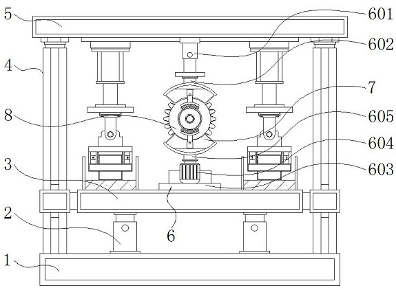
[0031] See Figure 1-7 The present invention provides a technical solution: a automatic clamping device having anti-static performance, including a base 1, a lifting column 2, a carrier, a strut 4, a top plate 5, a rotating mechanism 6, a hydraulic rod 601, Active shaft 602, motor mount 603, rotary electric machine 604, motor shaft 605, positioning clamping mechanism 7, carrier frame 701, carrier pad 702, gear groove 703, spring 704, positioning plate 705, fixed plate 706, first micro The telescopic rod 707, the first clamping plate 708, the conductive plastic 709, the processing member 8, the transfer belt 9, the motor mounting frame 10, the linear motor 11, the cylinder 12, the piston rod 13, the mounting plate 14, the feed clamping mechanism 15, The plate 1501, the rotary shaft 1502, the rotary plate 1503, the clamping frame 1504, the side plate 1505, the second micro telescopic rod 1506, the second clamping plate 1507, the outer mounting frame 16, and the hollow groove 17, the upper portion of the upper portion of the base 1 The raised column 2 is mounted, and the upper side of the lifting post 2 is attached, and both sides of the base 1 are fixed, and the struts 5 are fixed above, and the top plate 5 is fixed, the rotating mechanism 6 is located at the carrier 3. Above the middle, and the rotating mechanism 6 includes a hydraulic rod 601, a movable shaft 602, a motor mount 603, a rotary electric machine 604, and a motor shaft 605, and a hydraulic rod 601 is mounted below the central portion of the top plate 5, and the lower side of the hydraulic rod 601 is provided. The active shaft 602 is fixed above the middle of the carrier 3, and the motor mount 603 is attached, and the motor mount 604 is mounted, and the motor shaft 605 is provided above the rotary electric machine 604, and the upper side and activity of the motor shaft 605. The lower side of the shaft 602 is fixed to the positioning clamping mechanism 7, and the positioning holding mechanism 7 is provided with two sets of two sets, and the symmetric center of the positioning holding mechanism 7 is coincident with the symmetric center of the processing member 8, and the positioning clamping mechanism 7 passes The rotating motor 604 and the motor shaft 605 and the motor shaft 605 constitute a rotatable structure between the carrier 3, and the upper and lower sets of symmetrical set positioning clamping mechanism 7 facilitates uniform and stable clamping of the central processing member 8, through the rotary electric machine 604 and the motor shaft. 605 Even if the rotation of the positioning clamping mechanism 7 and the processing member 8, the steering of the processing member 8 is to facilitate the use of the feed clamping mechanism 15 on both sides.
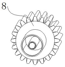
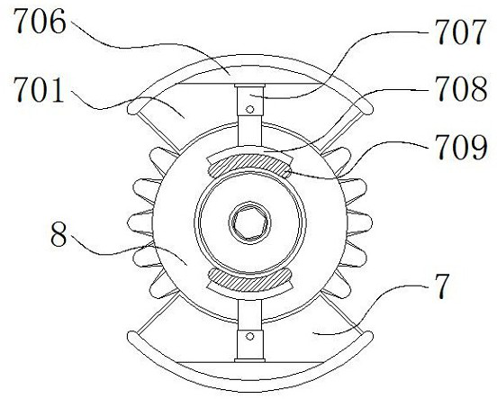
[0032] The positioning clamping mechanism 7 includes a carrier 701, a carrier pad 702, a gear groove 703, a spring 704, a positioning plate 705, a fixing plate 706, a first micro telescopic rod 707, a first clamping plate 708, and a conductive plastic 709, The carrier pad 702 is fixed, and the inner portion of the carrier pad 702 is provided with a gear groove 703, and the inner upper wall of the carrier frame 701 is mounted, and the inner side of the spring 704 is fixed, the positioning plate 705 is fixed. The fixing plate 706 is connected to the outer side of the frame 701, and one side of the fixing plate 706 is mounted, and the first micro-telescopic rod 707 is fixed, and the first clamping plate 708 is fixed, and the first clip is The inner side of the panel 708 is provided with a conductive plastic 709, the carrier frame 701 is in a arc shape structure, and the carrier pad 702 inside the carrier box 701 is modeled with a gear groove 703, and the gear groove 703 and the gear of the gear groove 703 and the processing member 8 are between the gear grooves 703 The shape is compact, and the carrier frame 701 of the arc shape structure can carry out the outer side of the processing member 8, and the gear groove 703 in the inner equidistant provided by the bearer pad 702 is convenient to fit the external gear position of the processing member 8, The first clamping plate 708 and the conductive plastic 709 are all arc-shaped, and the first clamping plate 708 constitutes a telescopic structure between the first micro-telescopic rod 707 and the fixing plate 706, easy to telescopic through the first micro-telescopic rod 707. The position of the first clamping plate 708 is adjusted, the first clamping plate 708 and the conductive plastic 709 of the arc shape structure can be clamped outside the side connecting tube of the processing member 8, wherein the conductive plastic 709 has good elasticity, use The characteristics of light and discharge static electricity are suitable for the electrostatic sensitive processing member 8.
[0033] A processing member 8 is provided between the positioning clamping mechanism 7, and the transmission belt 9 is disposed on both sides of the carrier 3, and the conveyor belt 9 is "U" shape structure, and the symmetric center of the conveyor belt 9 and the symmetric center of the carrier 3 The conveyor belt 9 in which the "U" shape structure is used to perform automatic delivery of the processing member 8, one side of the "U" structure is used for the upper, one side for the following, "U" shaped curve above the curve The mounting count sensor can be corresponding to the mounting member 8, and the motor mounting frame 10 is mounted on both sides of the top plate 5, and the inside of the lower side of the motor mounting frame 10 is mounted, and the straight motor 11 is below the linear motor 11. The cylinder 12 is fixed, and the lower side of the cylinder 12 is provided with a piston rod 13, and the mounting plate 14 is fixed below the piston rod 13, and the feed clamping mechanism 15, the mounting plate 14, and the feed clamping mechanism is mounted below the mounting plate 14. 15 constitutes a lifting structure between the cylinder 12 and the piston rod 13 and the linear motor 11, and the cylinder 12 constitutes a laterally moving structure between the line motor 11 and the motor mounting frame 10, and passing through the linear motor 11 inside the motor mounting frame 10 The movement facilitates the lateral movement of the cylinder 12 and the piston rod 13 to facilitate moving the lower mounting plate 14 and the feed clamping mechanism 15 to the side of the positioning holder 7 performs corresponding clamping portions, through the cylinder 12 and The piston rod 13 is facilitated to drive the mounting plate 14 and the movable elevator 15 to facilitate clamping of the processing member 8 above the transfer belt 9 using the feed clamping mechanism 15 to hold up and down.
[0034] The feed clamping mechanism 15 includes an adapter plate 1501, a rotating shaft 1502, a rotating plate 1503, a clamping frame 1504, a side plate 1505, a second micro-telescopic rod 1506, and a second clamping plate 1507, and the mounting plate 14 is fixed. The board 1501, and the lower side of the adapter plate 1501 is mounted by the rotating plate 1503, and the clamping frame 1504 is fixed under the rotary plate 1503, and the side plate 1505 is fixed, and the side plate 1505 is fixed. The second micro-telescopic rod 1506 is attached to the inner side of 1505, and the top end of the second micro-telescopic rod 1506 is fixed to the second clamping plate 1507, the rotary plate 1503 and the clamping frame 1504 constitute rotation between the rotation shaft 1502 and the adapter plate 1501. The structural, and the second minute telescopic rod 1506 and the second clamping plate 1507 are mounted in the inner side of the rotary plate 1503, and the position of the second clamping plate 1507 is facilitated by the second micro-telescopic rod 1506, so that two groups are symmetrical. The arc-shaped second clamping plate 1507 is provided to hold the outer connection pipe of the processing member 8, which is easy to drive the rotation of the rotating plate 1503 by the axis of rotation 1502 and the electric motor thereof. The steering of frame 1504 and its internal processing member 8 can automatically realize full mechanical clamping feed, which is more flexible, and no need to manually assist in clamping, the top plate 5 is adjacent to the side of the transmission belt 9 arcuate corners. 16, and the outer mounting frame 16 is provided with a hollow groove 17 on one side of the positioning clamping mechanism 7.
[0035] In summary, the machining is used for automatic clamping devices having anti-moving properties. The process piece 8 is first performed by a transmission belt 9 presenting "U" shaped structure, wherein the "U" structure side is used. On the upper, one side is used for the following, and the mounting count sensor is corresponding to the curve of the "U"-shaped structure to avoid the drain-absorbing process 8, and then drive the mounting plate 14 through the cylinder 12 and the piston rod 13. The activity of the feeding clamping mechanism 15 lifted to facilitate the use of the feed clamping mechanism 15, and the position of the second clamping plate 1507 is adjusted by the second minute retracting rod 1506, so that the two sets of symmetrical set of arc shapes The panel 1507 is sandwiched in the outside of the side connecting tube of the processing member 8, and then the rotation of the rotating shaft 1502 and the rear side thereof facilitates the rotation of the rotating plate 1503, thereby driving the clamping frame 1504 and its internal processing members. 8 Turn to the positioning clamping mechanism 7 side, finally by the cylinder 12 and the piston rod 13, the processing member 8 sandwiched by the feed holding mechanism 15 rises to the positioning clamping mechanism 7, and then passes through the linear motor 11 in the motor. The left and right movement of the frame 10 moves the lateral movement of the cylinder 12 and the piston rod 13 to facilitate moving the lower mounting plate 14 and the feed clamping mechanism 15 to the side of the positioning holding mechanism 7 for respective clamping. Implement the above operation.
[0036] During the handover, the processing member 8 is placed to the lower positioning mechanism 7, and the carrier frame 701 of the arc shape structure can carry the outer side of the processing member 8, and the gear set by the inner equidistant inner isometric pad 702. The groove 703 can fit the outer gear position of the external gear of the processing member 8, which allows the positioning plate 705 to further elastic clamping fixation of the positioning plate 705 to the inner end position of the machining member 8, wherein the carrier pad 702 and the positioning plate. The 705 is located at different levels of height, both of which, then then adjusts the position of the first clamping plate 708 by the first micro-telescopic rod 707, the first clamping plate 708 and the conductive plastic 709 of the arc shape structure can be The outer connection of the connecting member 8 is formed externally, and the position of the positioning clamping mechanism 7 is adjusted by the hydraulic rod 601, so that the positioning clamping mechanism 7 of the upper and lower sets of symmetrical settings can be in the middle. The processing member 8 performs uniform and stable clamping, so that the clamping is more stable, wherein the conductive plastic 709 has good elasticity, characteristics of light and discharge static electricity, suitable for electrostatic sensitive processing members 8.
[0037] It can then be rotated by the rotating motor 604 and the motor shaft 605 and the rotation of the processing member 8, while the upper positioning clamping mechanism 7 can be rotated by the mating of the movable shaft 602, thereby facilitating the processing member 8 The steering, where the top plate 5 is mounted on one side of the conveyor belt 9 curved corners, and the inside of the outer mounting frame 16 can correspond to the corresponding supporting process or detecting device, wherein the processing means or detecting device can By contacting the processing member 8 between the spacer 17 and the positioning holding mechanism 7, it is convenient to perform corresponding processing or detection of the processing member 8, and finally refer to the above steps, the feed clamping mechanism 15 on the other side is achieved. The material is operated, and the processing piece 8 is continuously delivered by the transmission belt 9, in order to complete the entire mechanical processing of automatic clamping devices having anti-static properties.
[0038] The above, only the preferred embodiments of the present invention, but the scope of the invention is not limited thereto, and any skilled in the art is hereby disclosed in the technical solutions, according to the present invention. Inventive concepts are equivalent to alternative or change, it should be covered within the scope of the invention.

PUM

no PUM

Description & Claims & Application Information

We can also present the details of the Description, Claims and Application information to help users get a comprehensive understanding of the technical details of the patent, such as background art, summary of invention, brief description of drawings, description of embodiments, and other original content. On the other hand, users can also determine the specific scope of protection of the technology through the list of claims; as well as understand the changes in the life cycle of the technology with the presentation of the patent timeline. Login to view more.

Similar technology patents

Screw adjustable type clamping and fixing device for long block with bulged strip on top surface

InactiveCN108340299AEasy to process and inspectStrong and accurate clamping
Owner:DONGGUAN TIANHE ELECTROMECHANICAL DEV CO LTD

Classification and recommendation of technical efficacy words

  • Easy to process and inspect
  • Wide range of applications

Screw adjustable type clamping and fixing device for long block with bulged strip on top surface

InactiveCN108340299AEasy to process and inspectStrong and accurate clamping
Owner:DONGGUAN TIANHE ELECTROMECHANICAL DEV CO LTD

Multiple point touch localization method

InactiveCN101105733AWide range of applications
Owner:GUANGDONG VTRON TECH CO LTD
Why Eureka
Try Eureka