Eureka AIR delivers breakthrough ideas for toughest innovation challenges, trusted by R&D personnel around the world.

Micro-rib and air film hole combined cooling structure for turbine guider end wall

A technology of turbine guide and cooling structure, which is applied in the direction of machines/engines, stators, engine components, etc., and can solve the problems of increasing the robustness of the cooling structure of the end wall of the turbine guide and the influence of complex airflow conditions on the film cooling structure. To achieve the effect of enhancing the film cooling efficiency, avoiding layout requirements, and reducing the intensity of convective heat transfer

Pending Publication Date: 2022-01-21
AIR FORCE UNIV PLA
View PDF0 Cites 0 Cited by
  • Summary
  • Abstract
  • Description
  • Claims
  • Application Information

AI Technical Summary

Problems solved by technology

[0005] The object of the present invention is to overcome above-mentioned deficiencies in the prior art, provide a kind of cooling structure that is used for the combination of the micro-rib of the end wall of the turbine guider and the air film hole, it has improved the external air film cooling structure of the end wall of the turbine guider easily Problems affected by complex incoming flow conditions, that is, to increase the robustness of the cooling structure of the end wall of the turbine guide, and effectively strengthen the film cooling effect of the end wall

Method used


Image

  • Micro-rib and air film hole combined cooling structure for turbine guider end wall
  • Micro-rib and air film hole combined cooling structure for turbine guider end wall
  • Micro-rib and air film hole combined cooling structure for turbine guider end wall

Examples


Embodiment Construction

[0033] It should be noted that, in the case of no conflict, the embodiments in the present application and the features in the embodiments can be combined with each other. In order to enable those skilled in the art to better understand the solution of the present invention, the following will be implemented in conjunction with the present invention The drawings in the examples clearly and completely describe the technical solutions in the embodiments of the present invention. Apparently, the described embodiments are only part of the embodiments of the present invention, not all of them. Based on the embodiments of the present invention, all other embodiments obtained by persons of ordinary skill in the art without making creative efforts shall fall within the protection scope of the invention.

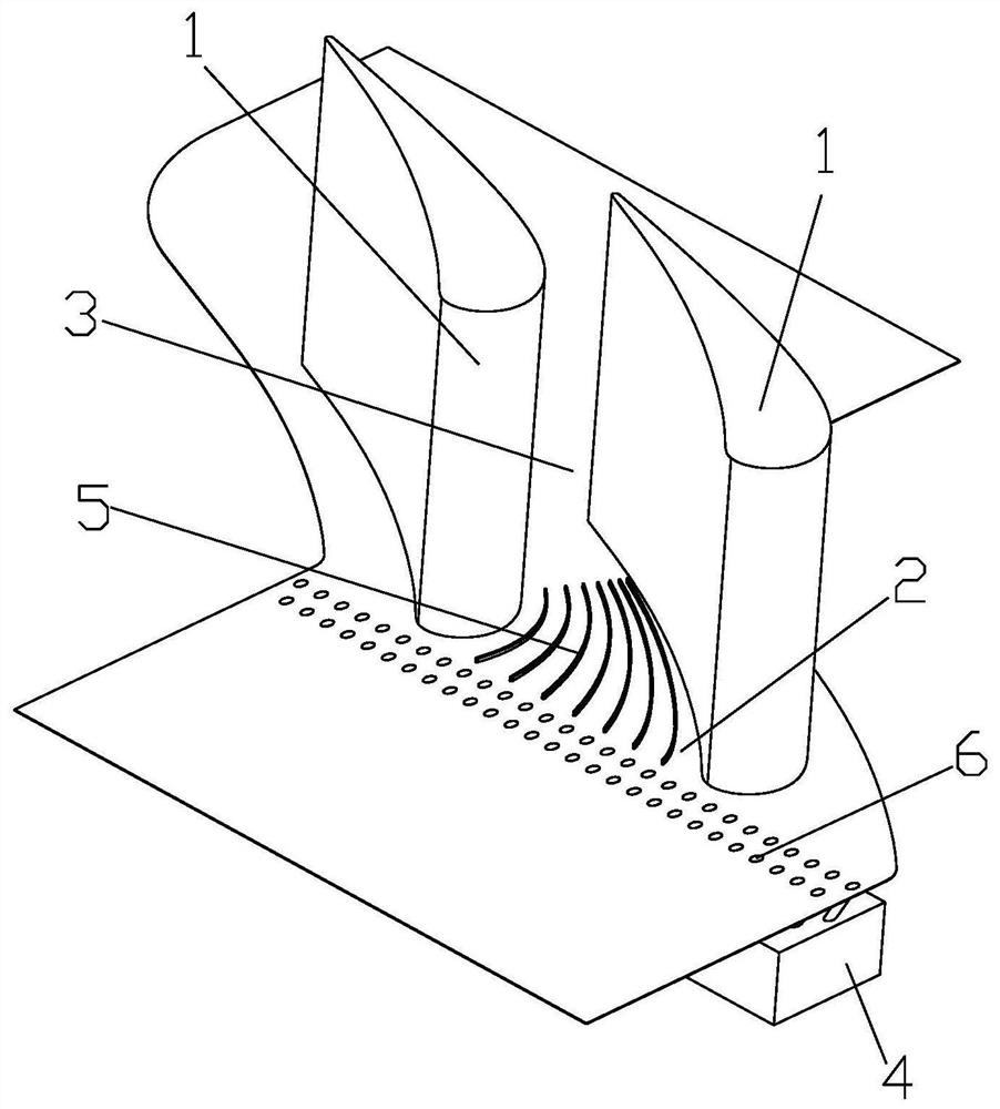
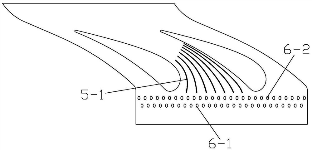
[0034] The turbine guide includes guide vanes 1, which are arranged on the end wall 2 of the guide vane. Between two adjacent guide vanes 1 is a channel 3 on the end wall of the guide...


PUM


Abstract

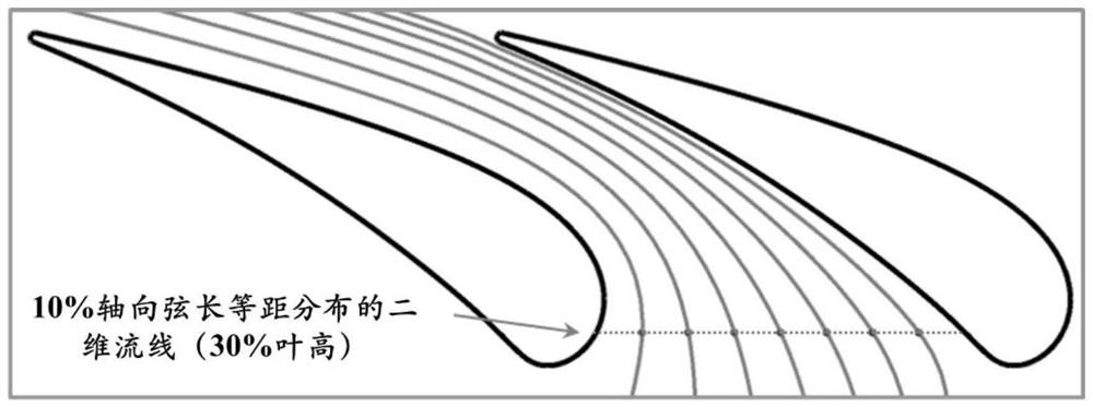
The invention discloses a micro-rib and air film hole combined cooling structure for a turbine guider end wall. The micro-rib and air film hole combined cooling structure comprises a micro-rib structure arranged on the guider end wall, wherein the micro-rib structure is positioned in a guider end wall channel at the downstream of an air film hole structure, and consists of multiple micro-ribs; and the micro-ribs are arranged according to a blade height section two-dimensional streamline distribution rule not disturbed by secondary currents in the guider channel. The micro-rib structure improves the problem of easy influence by complex incoming flow conditions on an external air film cooling structure of the turbine guider end wall, and effectively enhances the air film cooling effect of the end wall.

Description

technical field [0001] The invention belongs to the technical field of turbine blades of aero-engines and gas turbines, and in particular relates to a cooling structure for combining micro ribs and air film holes on the end wall of a turbine guide. Background technique [0002] As a key hot-end component of an aero-engine or a gas turbine, the turbine plays an important role in converting the thermal energy of the high-temperature gas at the exit of the combustor into mechanical energy. The most important heat-power conversion component in the turbine is the turbine blade, which works in a harsh environment of high temperature and high pressure. At present, the air intake temperature of high-pressure turbines of aero-engines is far higher than the temperature-resistant limit of turbine blades. Therefore, in order to ensure the safe and reliable operation of the turbine blades, the blades are arranged with a complex external film cooling structure and internal convective coo...

Claims


Application Information

Patent Timeline
Patent Type & Authority Applications(China)
IPC IPC(8): F01D9/02F01D25/12
CPCF01D9/02F01D25/12
Inventor 王志多吴兴彭靖波张驭张小博尉洋张斐
Owner AIR FORCE UNIV PLA
Why Eureka
Eureka Blog
Learn More