Gas turbine blade

a gas turbine blade and blade technology, applied in the direction of machines/engines, stators, liquid fuel engines, etc., can solve the problems of insufficient cooling of the airfoil leading edge in order to sufficiently reduce the temperature of the airfoil leading edge, insufficient cooling of the airfoil overall by the impingement cooling insert, etc., to achieve a lower consumption of cooling fluid for the cooling the effect of reducing the efficiency of the inner ring cooling

Inactive Publication Date: 2005-04-05
SIEMENS AG
View PDF9 Cites 55 Cited by
  • Summary
  • Abstract
  • Description
  • Claims
  • Application Information

AI Technical Summary

Benefits of technology

On the other hand, an embodiment of the invention is based on the observation that, although cooling solely by an impingement-cooling insert makes possible greater heat dissipation precisely at the airfoil leading edge due to the greater cooling capacity of the impingement cooling, cooling of the airfoil overall by the impingement-cooling insert is comparatively inefficient, since the cooling fluid absorbs less heat overall. For example, in a gas turbine blade cooled by cooling air and having meander cooling, the cooling fluid discharging from the trailing edge after passing through the meander passage is warmer than the cooling fluid likewise discharging from a blade trailing edge after impingement cooling.

Problems solved by technology

Purely convective cooling by use of a cooling-fluid flow in the meander-passage section at the airfoil leading edge may possibly be insufficient in order to sufficiently reduce the temperature of the airfoil leading edge.
On the other hand, an embodiment of the invention is based on the observation that, although cooling solely by an impingement-cooling insert makes possible greater heat dissipation precisely at the airfoil leading edge due to the greater cooling capacity of the impingement cooling, cooling of the airfoil overall by the impingement-cooling insert is comparatively inefficient, since the cooling fluid absorbs less heat overall.

Method used


Image

  • Gas turbine blade
  • Gas turbine blade

Examples


Embodiment Construction

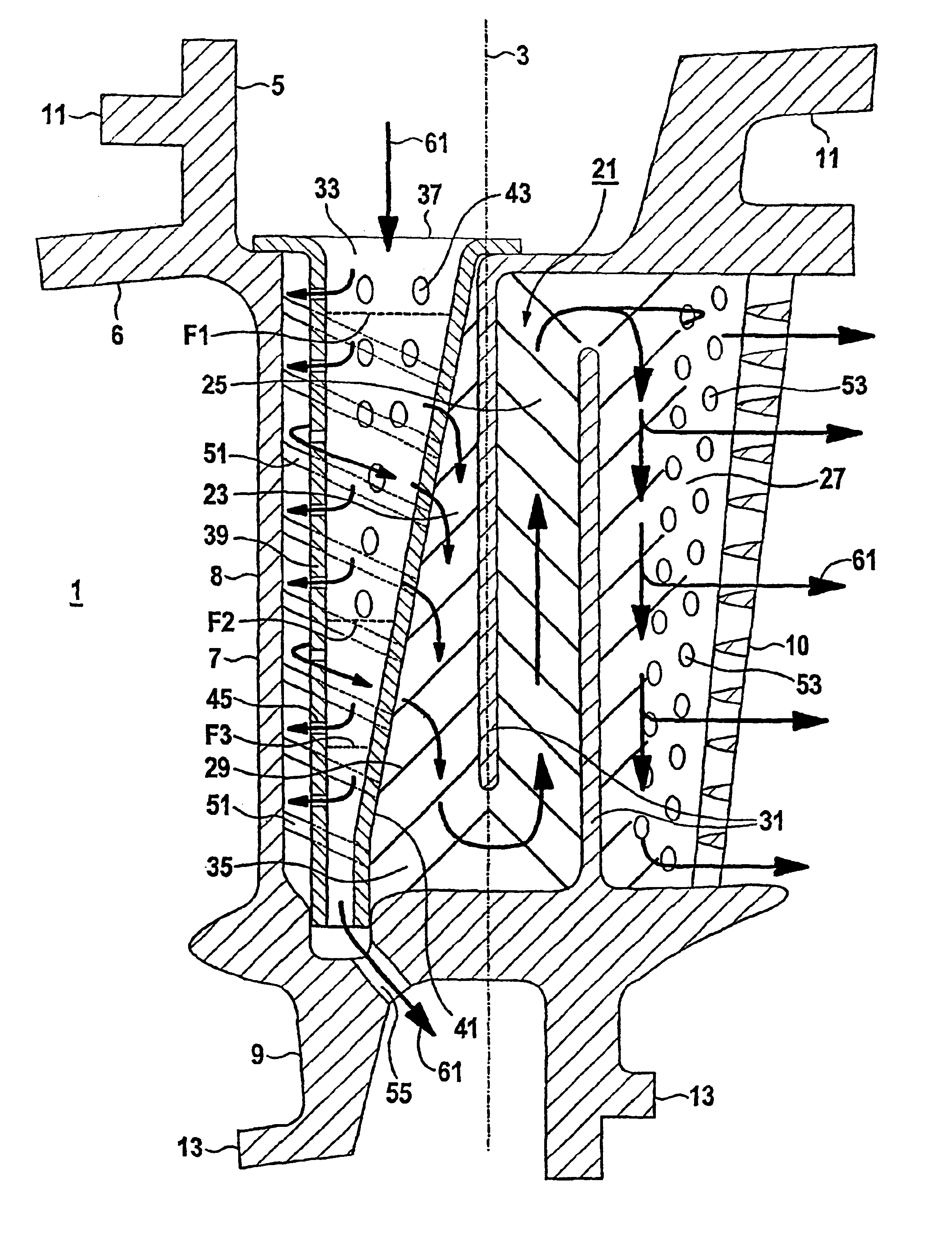
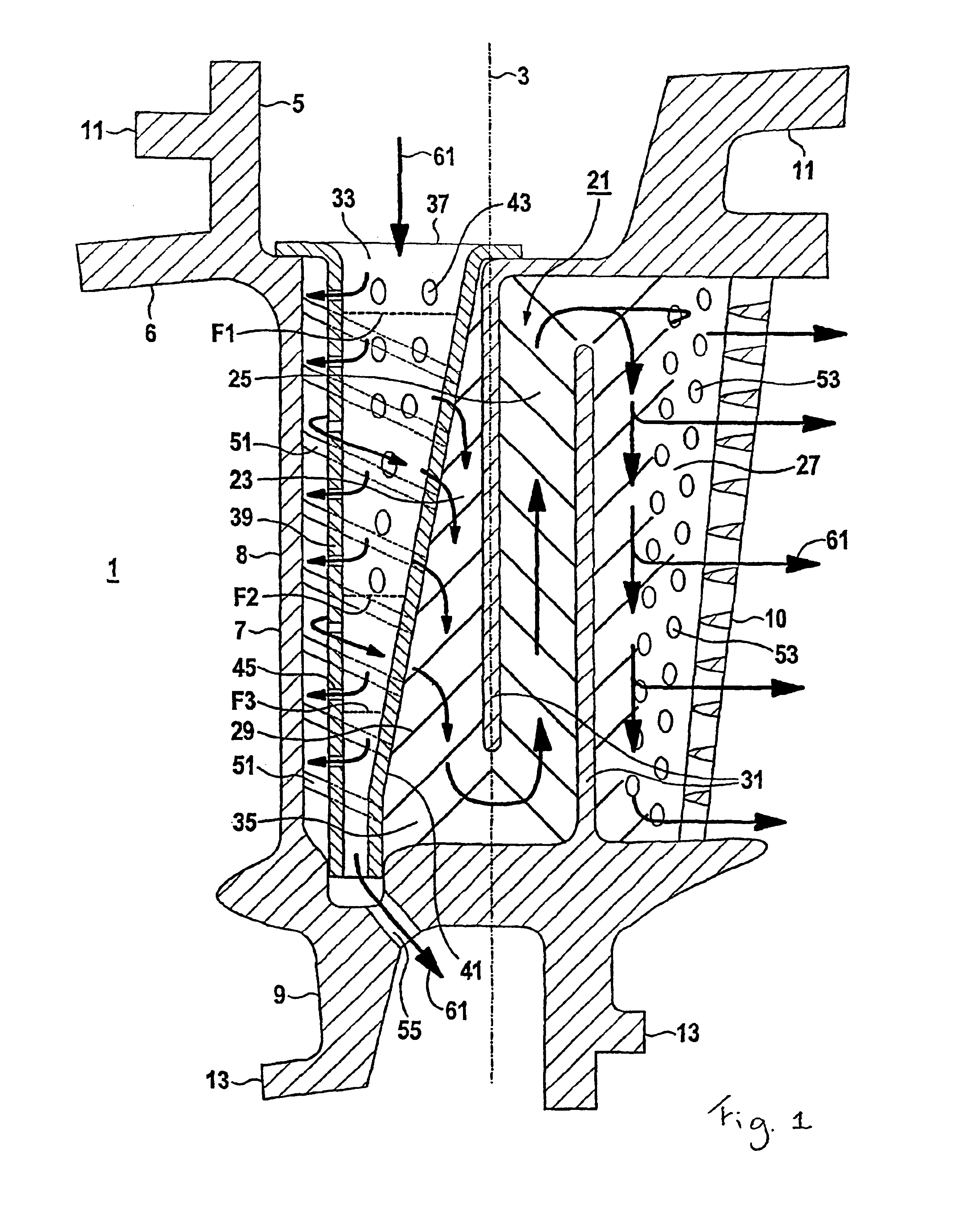
The gas turbine guide blade 1 is directed along a blade axis 3. Along the blade axis 3, the gas turbine blade 1 has, following one another, a fastening region 5, a platform region 6, an airfoil region 7 and an inner ring 9. The airfoil region 7 has an airfoil leading edge 8 and an airfoil trailing edge 10. The fastening region 5 has a hook 11 for hooking the gas turbine blade 1 in a casing (not shown) of a gas turbine. The inner ring 9 has steps 13 for engaging in a sealing system for sealing off a hot-gas duct (not shown) of a gas turbine relative to a rotor (likewise not shown) of the gas turbine. The gas turbine blade 1 is of hollow design. An internal cooling system of the gas turbine blade 1 is explained in more detail below:

A meandering cooling passage 21 leads through the interior of the gas turbine blade 1. The meandering cooling passage 21 is composed of sections 23, 25, 27 directed along the blade axis 3. These sections 23, 25, 27 are separated from one another by ribs 31....


PUM


Abstract

A gas turbine blade includes a combined convective cooling effected by a meandering cooling channel and an impact cooling channel and an impact cooling effected via an impact cooling insert. The impact cooling insert is arranged inside a first partial section of the meandering cooling channel extending along the front edge of the blade pan. The impact cooling insert tapers along this first partial section.

Description

FIELD OF THE INVENTIONThe invention generally relates to a gas turbine blade. In one embodiment, it relates to one having an airfoil leading edge and an airfoil trailing edge and having an inner cooling structure, comprising a meandering cooling passage with sections directed along the blade axis for directing a cooling fluid from the airfoil leading edge to the airfoil trailing edge.BACKGROUND OF THE INVENTIONA hollow gas turbine blade which can be cooled by cooling air is disclosed in U.S. Pat. No. 5,468,125. The cooling air is blown into cooling chambers, running parallel to the blade axis, of the hollow gas turbine blade. There, passing through the chambers, it cools the hot surface of the gas turbine blade from the inside. The incoming cooling air not yet heated is first of all directed past the leading edge of the gas turbine blade, this leading edge being subjected to especially high temperatures and therefore having to be cooled in an especially efficient manner. After the c...

Claims


Application Information

Patent Timeline
Patent Type & Authority Patents(United States)
IPC IPC(8): F01D5/18F01D9/02
CPCF01D5/189F05D2260/201
Inventor TIEMANN, PETER
Owner SIEMENS AG
Why Eureka
Try Eureka