Air flow regulation system for exhaust stream oxidation catalyst

a technology of air flow regulation and exhaust gas, which is applied in the direction of non-fuel substance addition to fuel, machines/engines, mechanical equipment, etc., can solve the problems of reducing the efficiency of oxidation catalysts, and reducing the degradation of exhaust gas temperatures. , to achieve the effect of enhancing the performance of oxidation catalysts, reducing the degradation of exhaust gas temperatures, and reducing the loss of catalytic conversion

Inactive Publication Date: 2006-08-17
CHAPEAU
View PDF14 Cites 54 Cited by
  • Summary
  • Abstract
  • Description
  • Claims
  • Application Information

AI Technical Summary

Benefits of technology

[0018] A system and method for dynamic regulation of air flow into the exhaust stream of an internal combustion engine upstream of an oxidation catalyst by means of a controlled feedback loop to ensure sufficient oxygen availability to provide optimum performance of an oxidation catalyst while simultaneously limiting the exhaust cooling effect of the incoming air stream to retard loss of catalytic conversion performance is provided. The engi

Problems solved by technology

Chief among these is failure of traditional energy producers to replace spent units and capitalize new plants.
These generation alternatives, however, have their own problems.
The impediment to widespread use is reliability, convenience, and trouble-free operation.
Unfortunately, the emissions associated with burning hydrocarbon fuels are generally considered damaging to the environment and the Environmental Protection Agency has consistently tightened emissions standards for new power plants.
Green house gases, as well as entrained and other combustion product pollutants, are environmental challenges faced by hydrocarbon-based units.
However, many of the markets that would be best served by the economics of engine-based co-generation have such poor air quality that strict exhaust emission limits have been instituted by air quality regulating agencies.
The exhaust emissions limits on oxides of nitrogen, carbon monoxide, and non-methane hydrocarbons are so restrictive that no technology exists to allow raw exhaust emissions from any engine operating on any hydrocarbon fuel to enter the atmosphere without exhaust aftertreatment which includes a nu

Method used


Image

  • Air flow regulation system for exhaust stream oxidation catalyst
  • Air flow regulation system for exhaust stream oxidation catalyst
  • Air flow regulation system for exhaust stream oxidation catalyst

Examples


Embodiment Construction

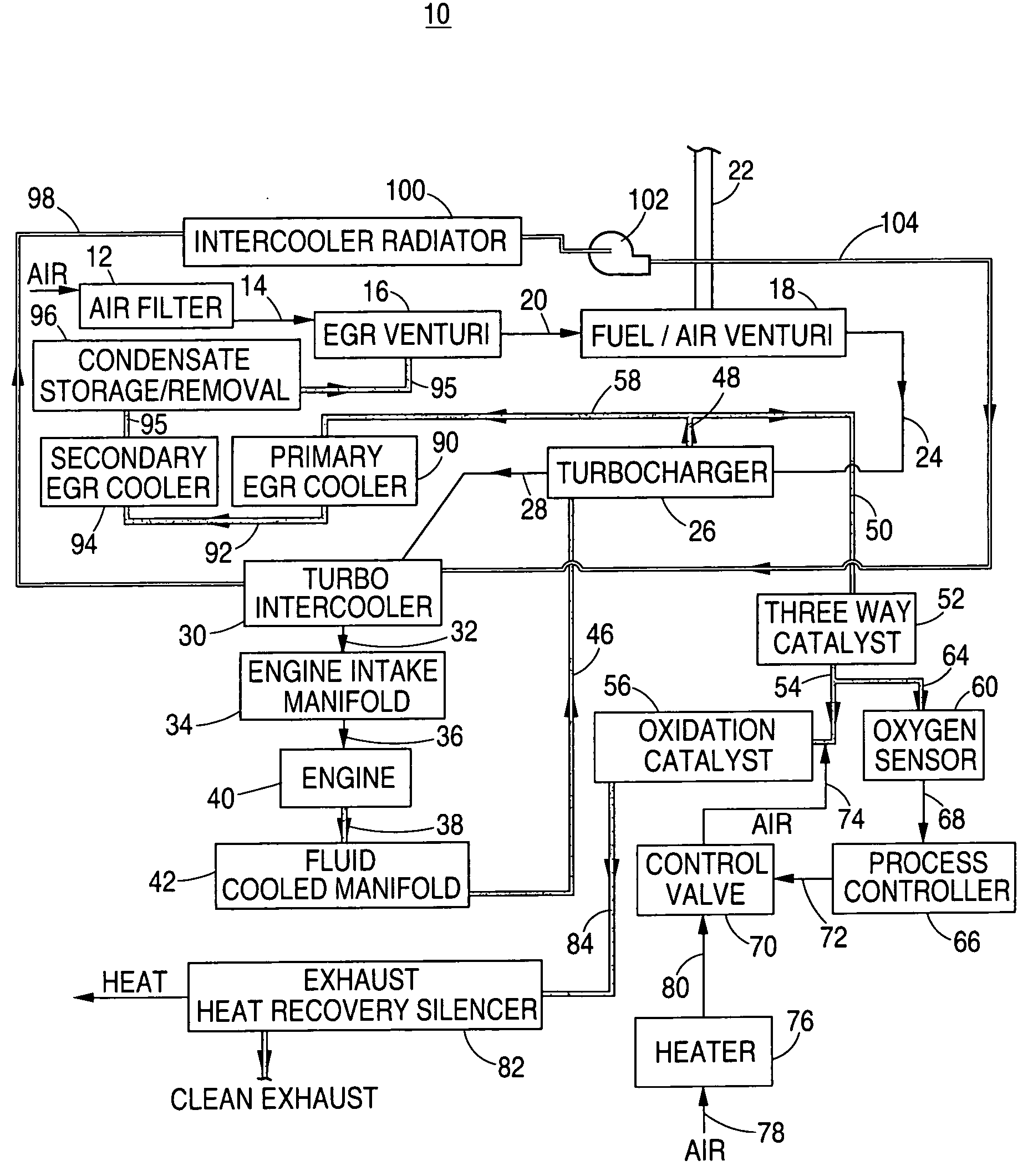
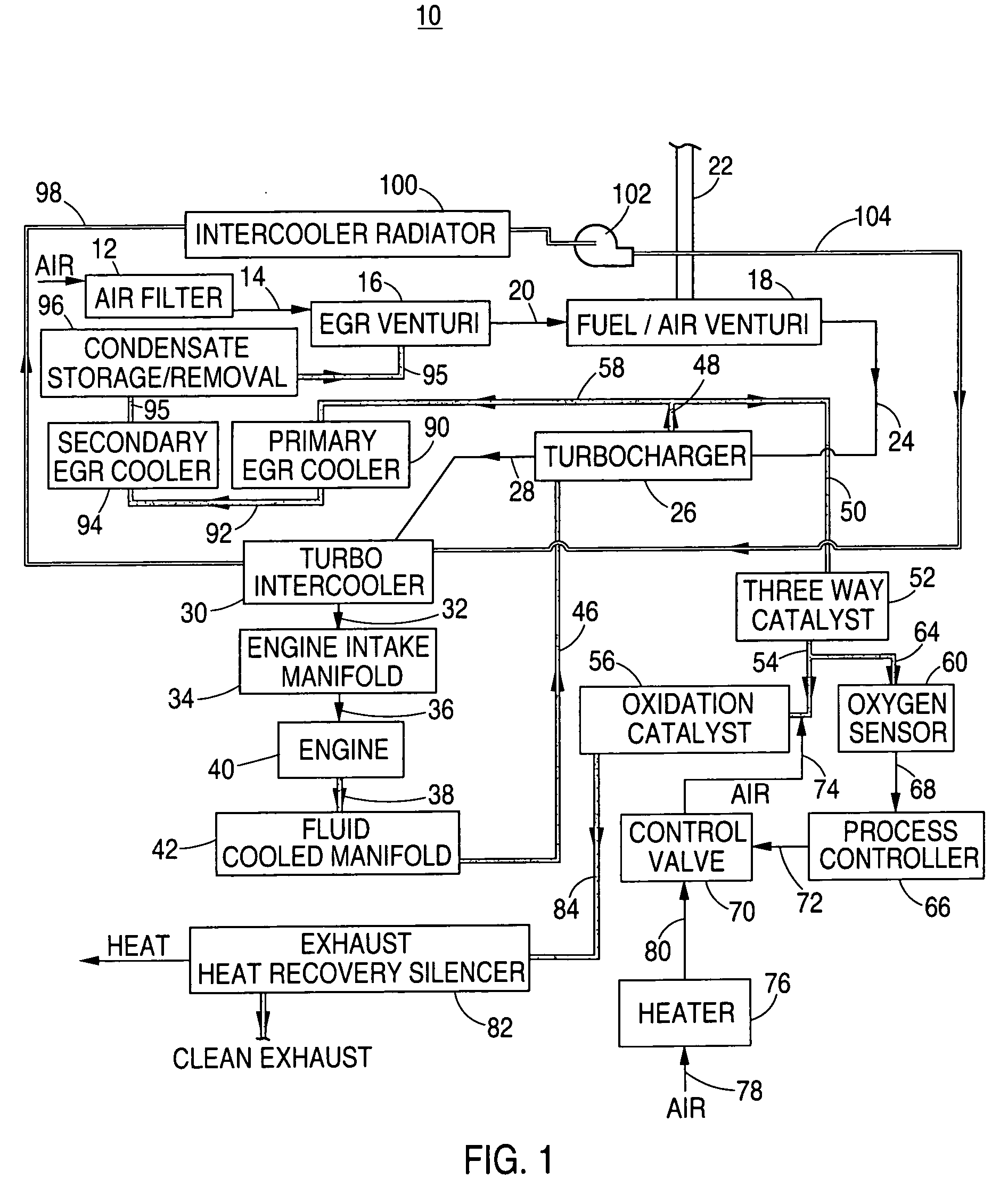
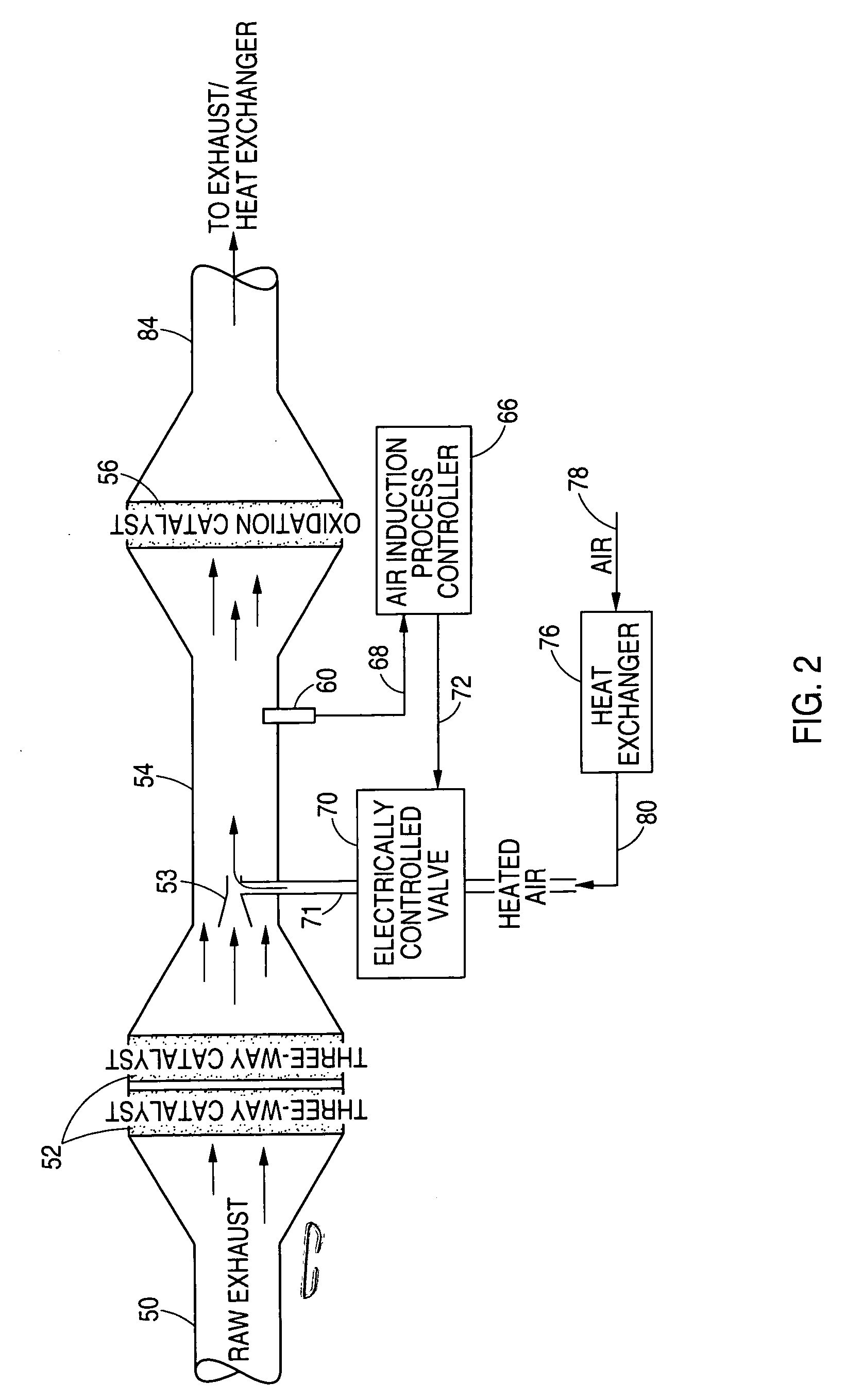
[0024] In accordance with the instant system and method, air flow into the exhaust gas stream of a reciprocating internal combustion engine, upstream of an oxidation catalyst, is regulated such that oxidation of carbon monoxide, hydrocarbons, and ammonia is achieved beyond the levels attainable and maintainable with a catalyst system that relies only upon pre-combustion air / fuel ratio management or the uncontrolled introduction of air. The modulation of air flow into the exhaust upstream of the oxidation catalyst via a controlled feedback loop, ensures sufficient oxygen availability to induce maximum oxidation of unwanted pollutants while simultaneously limiting the exhaust cooling effect of the incoming air stream and, thus, the associated loss of catalytic conversion performance, as well as the loss of recoverable heat from the exhaust stream for combined heat and power applications.

[0025] Exemplary of one system, a natural gas fueled, internal combustion engine, employing exhaus...


PUM


Abstract

An air flow regulation system for enhancing the performance of oxidation catalyst in the exhaust stream of an internal combustion engine is provided wherein air flow into the exhaust upstream of an oxidation catalyst is dynamically controlled via a controlled feedback loop to ensure sufficient oxygen availability to induce enhanced oxidation catalyst performance while simultaneously limiting the exhaust cooling effect of the incoming air stream and the associated loss of catalytic conversion performance. The modulation of air temperature and flow into the exhaust gas stream of a reciprocating internal combustion natural gas fuel engine upstream of an oxidation catalyst is regulated such that oxidation of carbon monoxide, hydrocarbons, and ammonia is achieved to a level beyond the levels attainable and maintainable with a catalyst strategy that relies only upon pre-combustion air/fuel ratio management. In one aspect, the modulation of air flow into the exhaust is via an electronically controlled feedback loop. In another aspect, the induced air is heated to assure catalyst performance and retard the loss of recoverable heat from the exhaust stream for combined heat and power applications.

Description

CROSS-REFERENCE TO RELATED APPLICATIONS [0001] The present application is a Continuation-in-Part of U.S. application Ser. No. 11 / 317,134 filed Dec. 23, 2005 for “EGR Cooling and Condensate Regulation System For Natural Gas fired Co-Generation Unit” which is a continuation of application Ser. No. 10 / 867,926 filed Jun. 6, 2004 for “EGR Cooling and Condensate Regulation System for Natural Gas Fired Co-Generation Unit,” now U.S. Pat. No. 6,978,772, which is a continuation-in-part of U.S. application Ser. No. 10 / 361,538 filed Feb. 10, 2003 for “Fuel Regulator for Natural Gas Fired Co-Generation”, now U.S. Pat. No. 6,748,932, and U.S. application Ser. No. 10 / 838,126 filed May 3, 2004, now abandoned, which is a continuation of U.S. application Ser. No. Ser. No. 10 / 356,826 filed Feb. 3, 2003 for “Heat Transfer System for Co-Generation Unit,” now U.S. Pat. No. 6,729,133, all of said applications are herein incorporated by reference in their entirety.BACKGROUND [0002] The present system relat...

Claims


Application Information

Patent Timeline
IPC IPC(8): F01N3/00F02M25/06F01N3/10
CPCF01N3/2006F01N3/22F01N3/225F01N3/306F02B29/0443F02B37/00F02M25/0709F02M25/0722F02M25/073F02M25/0732F02M25/074Y02T10/121Y02T10/26F01N13/009F01N13/0097F02M26/06F02M26/19F02M26/24F02M26/27F02M26/35Y02T10/12
Inventor ROSER, RANSON R.
Owner CHAPEAU
Why Eureka
Try Eureka