Photocatalyst materials having semiconductor characteristics and methods for manufacturing and using the same

a photocatalyst and semiconductor technology, applied in the field of air purification technology, can solve the problems of reducing the powerful oxidation capacity of the activated photocatalyst, the sol-gel doping method is a complicated and long process, and the prior art technique suffers from numerous limitations, drawbacks and disadvantages, etc., to achieve rapid and effective oxidation, strong oxidation capability, effective decomposition and removal from the environment

Inactive Publication Date: 2007-08-23
SAMSUNG ELECTRONICS CO LTD
View PDF14 Cites 22 Cited by
  • Summary
  • Abstract
  • Description
  • Claims
  • Application Information

AI Technical Summary

Benefits of technology

[0006]When the photocatalytic material is activated by light energy, the electrons generated tend to form “super oxide” anions (typically represented as O2−) and the holes form hydroxide (OH−) radicals, with the result that the activated photocatalyst has an unusually strong oxidation capability. Specifically, the O2− and OH− radicals are capable of rapidly and effectively oxidizing an organic contaminant contacted at the surface of the photocatalyst thereby converting the contaminant into water (H2O) and carbon dioxide (CO2) or, sometimes, to small amounts of relatively harmless mineral acids, for example HCl. Thus, volatile organic contaminants in an air stream can be effectively decomposed and removed from the environment by contacting the air stream with the light-activated photocatalyst.

Problems solved by technology

As also taught in the art, however, the electrons and holes generated by exciting a photocatalyst with light energy have a tendency to quickly recombine thereby neutralizing the powerful oxidation capacity of the activated photocatalyst.
By comparison with the dipping method, however, the Sol-gel doping method tends to be a very complicated and lengthy (slow) process.
This prior art technique, however, suffers from numerous limitations, drawbacks and disadvantages.
One important drawback of the prior art approach is the high costs of the materials.
Nobel metals such as Pt, Au, and Ag are also precious metals, which are very expensive.
Even the metal alkoxide precursors are relatively expensive industrial commodities.
A second disadvantage of the prior art technique is that it is relatively complicated—involving preparation of two precursors—and relatively lengthy.
Another important limitation of the above-described conventional method, however, is that it is very difficult, if not impossible, to reliably prepare nano-sized metal oxide particles for use as the photocatalyst using the metal alkoxide precursor technique.
This process, however, requires relatively complex production equipment, does not insure a thorough, homogeneous doping of the TiO2, and does not produce optimally-sized photocatalyst particles.
This process, however, employs relatively uncommon and expensive “inner-transition” lanthanide series elements and relatively high processing temperatures in both the drying and calcination steps.

Method used


Image

  • Photocatalyst materials having semiconductor characteristics and methods for manufacturing and using the same
  • Photocatalyst materials having semiconductor characteristics and methods for manufacturing and using the same
  • Photocatalyst materials having semiconductor characteristics and methods for manufacturing and using the same

Examples


example 1

[0060]This illustrative example demonstrates the preparation of a first photocatalyst in accordance with this invention. The completed first photocatalyst consists essentially of titanium dioxide (TiO2) with interstitial iron (Fe) ions dispersed through the TiO2 lattice.

[0061]Four aqueous solutions of iron chloride (FeCl2) in distilled water were prepared as follows:

[0062]Example 1a: 0.1 mol % FeCl2

[0063]Example 1b: 0.5 mol % FeCl2

[0064]Example 1c: 1 mol % FeCl2

[0065]Example 1d: 10 mol % FeCl2

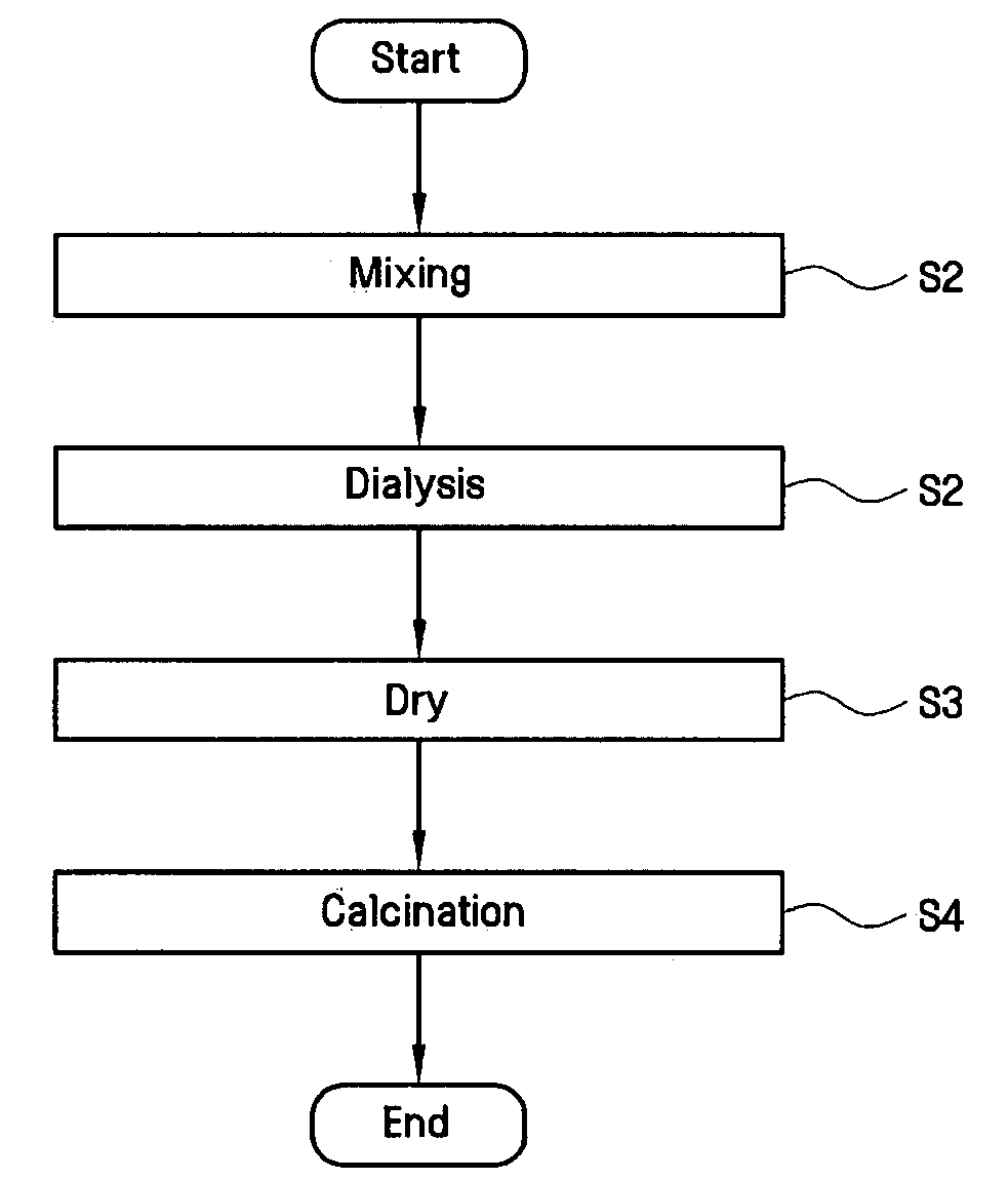
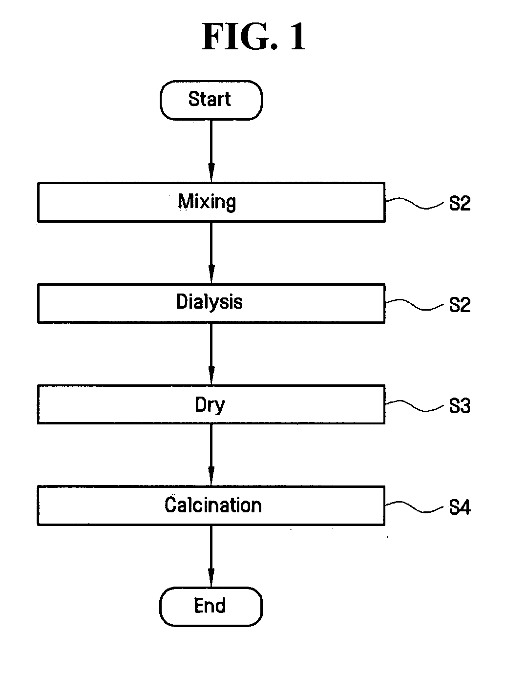
[0066]Titanium chloride (TiCl4) was mixed into each of the four iron chloride solutions (step S1) and allowed to mix for a period of about 1 hour. Next, the S2 dialysis step was performed on each of the four mixtures for a period of about 1 hour in order to form sols. Next, the S3 vacuum drying step was performed on each of the four sols at a pressure of about 103 to 104 torr and at a temperature of about 10° C. to about 20° C.

[0067]The resulting four photocatalyst products were each divide...

example 2

[0068]This illustrative example demonstrates the preparation of a second photocatalyst in accordance with this invention. The completed second photocatalyst consists essentially of titanium dioxide (TiO2) with interstitial tungsten (W) ions dispersed throughout the TiO2 lattice. This example was carried out in the same manner as described above for Example 1 except that four aqueous solutions of tungsten chloride (WCl2) were substituted for the aqueous solutions of iron chloride. These sixteen completed photocatalyst products were used to carry out subsequent experimental testing as described below.

example 3

[0069]This example illustrates the relationship between mean particle size of the photocatalyst and the concentration of the second metal ion under conditions of different calcinations step temperatures. In these tests, particle sizes were measured using a dynamic light scattering method. The results of this experimental testing are illustrated in FIGS. 3A to 3D, as described below.

[0070]FIG. 3A shows the relationship between mean particle size and the second-metal ion concentration for the iron-doped and tungsten-doped titanium dioxide photocatalysts of Examples 1 and 2 “before calcination.”FIG. 3A shows that, at each of the four tested mol % concentrations for both the iron-doped and tungsten-doped photocatalysts, the mean particle size was well below 10 nm. FIG. 3B shows similar results but with slightly higher mean particle sizes following calcination at 100° C. FIG. 3C also shows results generally similar to FIGS. 3A and 3B with calcination carried out at 300° C.; but in FIG. 3...


PUM

PropertyMeasurementUnit
mean particle diameteraaaaaaaaaa
temperatureaaaaaaaaaa
pressureaaaaaaaaaa

Abstract

New types of photocatalyst materials are disclosed together with methods for preparing and using these materials, as well as air treatment systems incorporating such materials. The photocatalyst materials of this invention consist essentially of very small particles of a first-metal oxide, the first-metal being a metal that exhibits photo-induced semiconductor properties, having ions of a second-metal dispersed throughout its lattice structure, the second-metal being selected from the group of dopant metals. Such photocatalyst materials are prepared by the steps of mixing first-metal and second-metal precursors, removing nonessential ions from the mixture, drying the resulting product, and calcinating the dried product to produce the completed photocatalyst material.

Description

CROSS-REFERENCE TO RELATED APPLICATIONS[0001]This U.S. non-provisional patent application claims priority under 35 U.S.C. § 119 of Korean Patent Application 10-2006-0015792 filed on Feb. 17, 2006, the entire contents of which are hereby incorporated by reference.BACKGROUND OF THE INVENTION[0002]The subject matter described herein is generally concerned with air purification technology that employs new and improved photocatalyst materials especially efficient in decomposing volatile organic compounds that may be present in an air stream, with methods for manufacturing such photocatalyst materials, and with methods and apparatus for using such materials to clean and purify air streams. A specific application for the photocatalyst materials of this invention is to treat an air stream drawn from a “clean room” environment to remove and / or decompose organic contaminants before recycling the treated air stream back to the “clean room.”[0003]It is known in the art of air purification to pr...

Claims


Application Information

Patent Timeline
Patent Type & Authority Applications(United States)
IPC IPC(8): C07C1/00B01J19/08
CPCB01D53/8687B01J37/30B01D2255/802B01D2257/708B01J21/06B01J21/063B01J23/22B01J23/30B01J23/34B01J23/745B01J23/80B01J23/835B01J35/0013B01J35/004B01D2255/20707Y02W10/37H01L21/02
Inventor HAM, DONG SEOKIHM, SON KIPARK, JOO ILCHOI, KWANG MINJEONG, KWANG EUN
Owner SAMSUNG ELECTRONICS CO LTD
Why Eureka
Try Eureka