Battery cooling structure

a battery and cooling structure technology, applied in the field of battery cooling structure, can solve the problems of reducing capacity, degrading durability, and difficulty in cooling, and achieve the effects of reducing dimensions, simplifying the battery case, and ensuring a degree of freedom in the layou

Inactive Publication Date: 2005-07-14
HONDA MOTOR CO LTD
View PDF4 Cites 55 Cited by
  • Summary
  • Abstract
  • Description
  • Claims
  • Application Information

AI Technical Summary

Benefits of technology

[0008] The present invention has been accomplished under the above-mentioned circumstances, and it is an object thereof to uniformly cool a lar

Problems solved by technology

Since the plurality of battery modules are arranged in multiple vertical rows and multiple tiers, and the cooling air flows from a front vertical row to a rear vertical row, the battery modules on the front vertical row side are cooled efficiently by contact with low temperature cooling air that has not yet carried out heat exchange, but the battery modules on the rear vertical row side contact cooling air whose temperature has been increased by heat exchange, so that they have difficulty to be cooled.
In this way, the dif

Method used


Image

  • Battery cooling structure
  • Battery cooling structure
  • Battery cooling structure

Examples


first embodiment

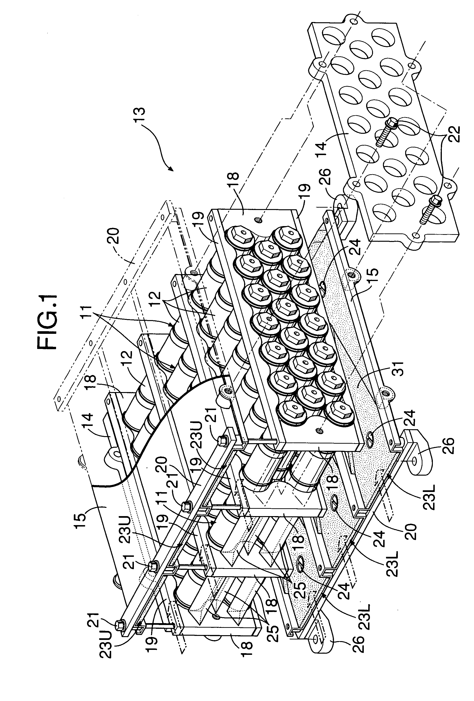
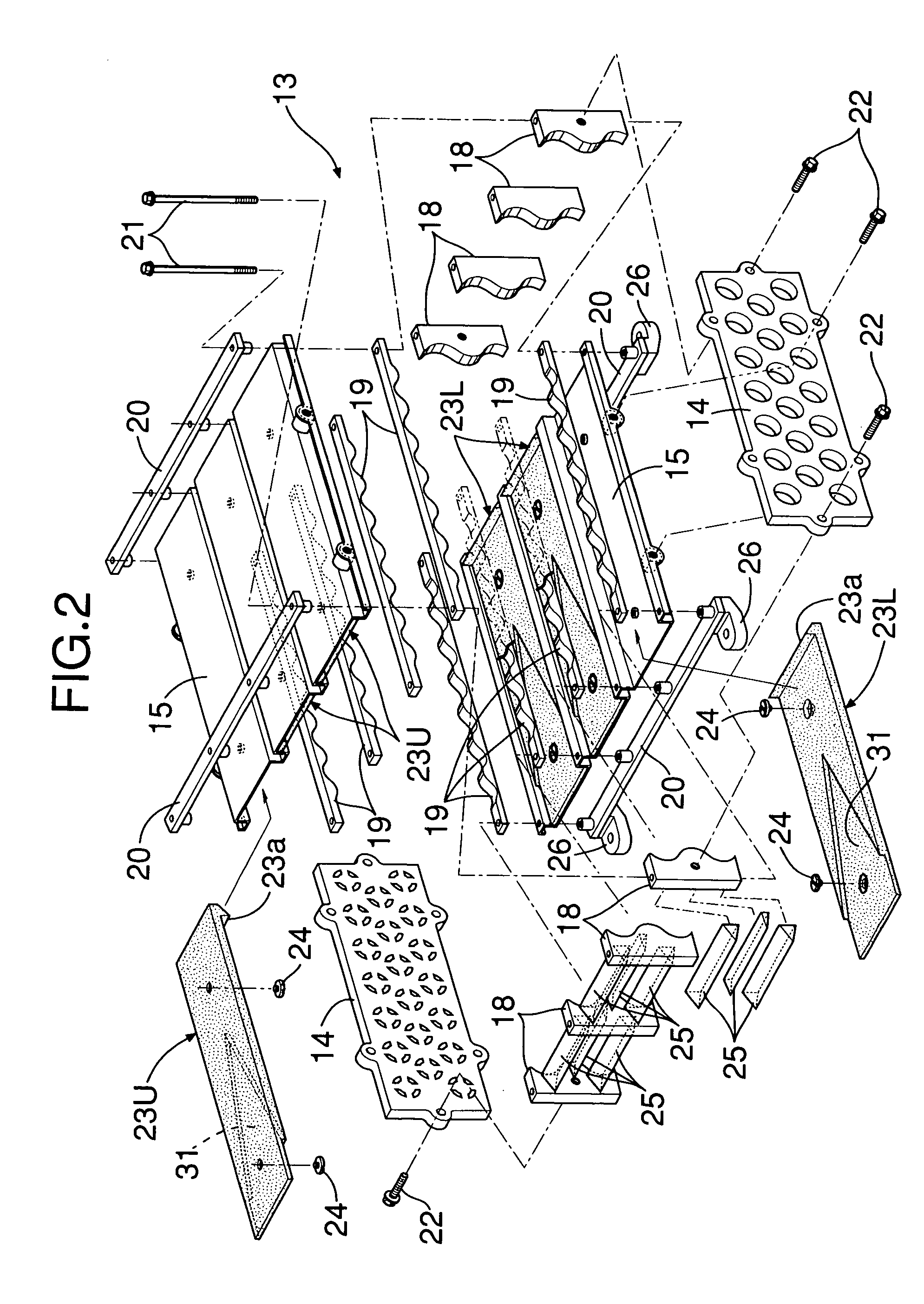
[0049] A first embodiment is now explained with reference to FIGS. 1 to 4C.

[0050] As shown in FIG. 1 and FIG. 2, a battery module 11, which serves as a power source for a hybrid vehicle motor / generator, is formed by integrally connecting together in series a plurality (six in this embodiment) of cylindrical battery elements 12 made of, for example, NiMH batteries into a rod shape, and twenty battery modules 11 are arranged in a staggered manner so that there are seven in an upper tier, six in a middle tier, and seven in a lower tier.

[0051] A battery case 13 for supporting the 20 battery modules 11 is made in the shape of substantially rectangular tube having a pair of rectangular first plates 14 forming left and right side faces of the battery case 13 and a pair of second plates 15 providing a horizontal connection between upper ends and between lower ends of the two first plates 14. Front and rear ends of the substantially rectangular tube-shaped battery case 13 are open; the fron...

fourth embodiment

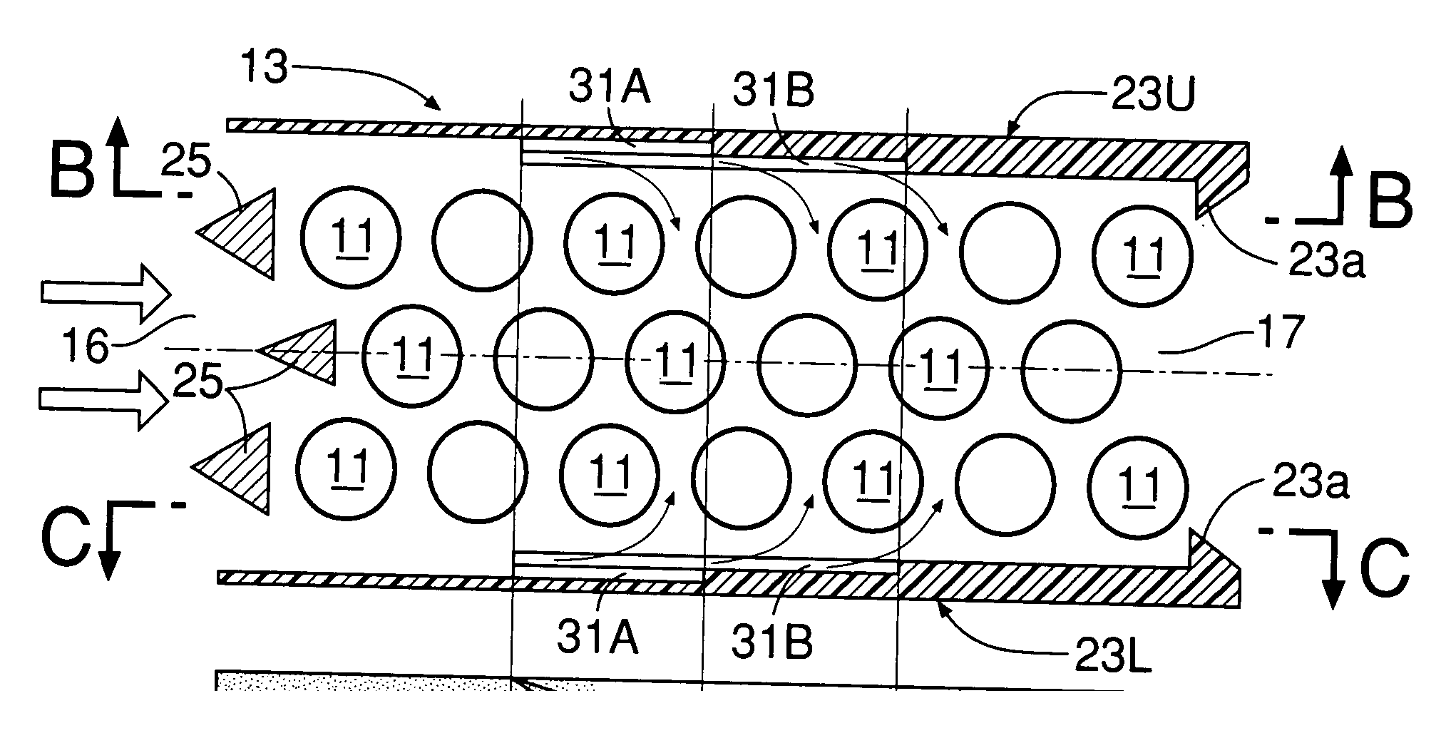
[0066]FIGS. 7A, 7B, and 7C show the present invention. Deep cooling air guide channels 31 are formed so as to have a depth of 11 mm in upper air guide plates 23U, and shallow ones are formed so as to have a depth of 5.5 mm in lower air guide plates 23L. As a result, the flow rate of the cooling air blowing down from the cooling air guide channels 31 of the upper air guide plates 23U is higher than the flow rate of the cooling air blowing up from the cooling air guide channels 31 of the lower air guide plates 23L, thereby preventing the flow of cooling air from becoming sluggish in the vicinity of the battery modules 11 in the middle tier, to enhance the cooling effect.

[0067] As is clear from Table 1, in the fourth embodiment the maximum temperature of the battery module 11 in the middle tier of the third vertical row from the front, which had the highest temperature, was decreased to 52.1° C. and the temperature difference was decreased to 6.3° C.

fifth embodiment

[0068]FIGS. 8A, 8B, and 8C show the present invention, in which the position of the downstream ends of cooling air guide channels 31 of lower air guide plates 23L are displaced, relative to the downstream ends of cooling air guide channels 31 of upper air guide plates 23U, to the upstream side by a distance corresponding to the pitch at which battery modules 11 are arranged in the front-to-rear direction. Since the positions of the upstream ends of tapered portions 31b of the upper and lower cooling air guide channels 31 are the same, an angle V of the lower cooling air guide channels 31 is larger than an angle V of the upper cooling air guide channels 31. As a result, the position at which the cooling air blows down from the cooling air guide channels 31 of the upper air guide plates 23U is displaced from the position at which the cooling air blows up from the cooling air guide channels 31 of the lower air guide plates 23L, thereby preventing the cooling air from the upper directio...


PUM


Abstract

In a battery cooling structure, a battery case housing a large number of battery modules is formed into the shape of a rectangular tube having a cooling air inlet and a cooling air outlet, and V-shaped cooling air guide channels having a decreasing flow-path cross sectional area are provided on inner faces of air guide plates that define upper and lower faces of the rectangular tube. The flow of cooling air is deflected by these V-shaped cooling air guide channels toward a central part on the downstream side, thus effectively cooling the battery modules disposed in the central part, for which the cooling effect is poor to make uniform the temperature of the battery modules, resulting in a suppressed variation in capacity and lifetime. Moreover, since it is not necessary to provide a bypass passage in the battery case, it is possible to simplify the structure of the battery case, reduce the dimensions, and improve the degree of freedom in the layout.

Description

RELATED APPLICATION DATA [0001] The Japanese priority application No. 2003-426515 upon which the present application is based is hereby incorporated in its entirety herein by reference. BACKGROUND OF THE INVENTION [0002] 1. Field of the Invention [0003] The present invention relates to a battery cooling structure in which a large number of rod-shaped battery modules are arranged in parallel to each other at predetermined intervals within a battery case, and these large number of battery modules are cooled with cooling air. [0004] 2. The Related Art [0005] Japanese Patent Application Laid-open Nos. 10-255859 and 11-329518 disclose an arrangement in which a long rod-shaped battery module is formed by connecting a plurality of battery elements together in series, and a large number of the battery modules are arranged in parallel to each other at predetermined intervals within a battery case, the arrangement being employed as an energy source for a motor for travel of an electric automo...

Claims


Application Information

Patent Timeline
IPC IPC(8): B60K1/04B60K11/06F25B21/02H01M10/60H01M10/613H01M10/617H01M10/625H01M10/643H01M10/651H01M10/6563H01M10/6566H01M50/213
CPCH01M2/105H01M2/1072H01M10/5004H01M10/5008H01M10/5073H01M10/503H01M10/5059H01M10/5063H01M10/5016H01M10/625H01M10/6557H01M10/643H01M10/617H01M10/6561H01M10/6566H01M10/613Y02E60/10H01M50/213
Inventor YAGI, KAZUHIKOKOIKE, EIJITAKEDOMI, HARUMINISHIBORI, TAKEO
Owner HONDA MOTOR CO LTD
Why Eureka
Try Eureka