
Wind turbine blade and wind turbine generator

A technology of wind turbines and generators, applied to wind power generation, wind engines consistent with the wind direction, wind engines, etc., can solve problems such as damage, bringing into the interior of the equipment, equipment damage, etc., to speed up the speed and prevent bird damage , To ensure the effect of safe operation of electricity

Pending Publication Date: 2022-01-21
黎阜南
View PDF1 Cites 0 Cited by
  • Summary
  • Abstract
  • Description
  • Claims
  • Application Information

AI Technical Summary

Problems solved by technology

[0004] In this invention, the main body of the protective equipment and the vibration-reducing clamping mechanism for clamping and fixing the main body of the generator are arranged so that the wind turbine generator can be clamped and fixed by the vibration-damping clamping mechanism during operation and use, and buffered normally. The vibration amplitude generated by the operation makes the main body of the generator in a nearly suspended state during normal operation, which can ensure the normal circulation of the air inside the main body of the protective equipment, so that the external air and the high-temperature air generated by the main body of the internal generator are alternately cooled and heated, which has a great impact on power generation. The main body of the generator performs excellent heat dissipation and cooling, but in actual use, when the external air enters the main body of the generator to radiate heat and ventilate the interior of the equipment, it will inevitably bring external dust into the interior of the equipment, causing damage to the equipment. Damage, if the gas entering the equipment is not cleaned, the main body of the generator will be damaged due to excessive dust inside after long-term use

Method used


Image

  • Wind turbine blade and wind turbine generator
  • Wind turbine blade and wind turbine generator
  • Wind turbine blade and wind turbine generator

Examples


Embodiment Construction

[0032] The following will clearly and completely describe the technical solutions in the embodiments of the present invention with reference to the accompanying drawings in the embodiments of the present invention. Obviously, the described embodiments are only some, not all, embodiments of the present invention. Based on the embodiments of the present invention, all other embodiments obtained by persons of ordinary skill in the art without making creative efforts belong to the protection scope of the present invention.

[0033]In describing the present invention, it is to be understood that the terms "center", "longitudinal", "transverse", "length", "width", "thickness", "upper", "lower", "front", " Back", "Left", "Right", "Straight", "Horizontal", "Top", "Bottom", "Inner", "Outer", "Clockwise", "Counterclockwise", etc. or The positional relationship is based on the orientation or positional relationship shown in the drawings, which is only for the convenience of describing th...


PUM


Abstract

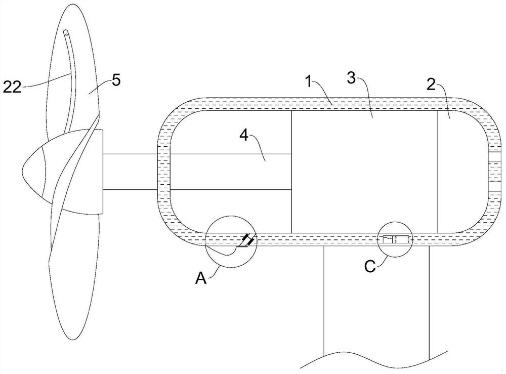
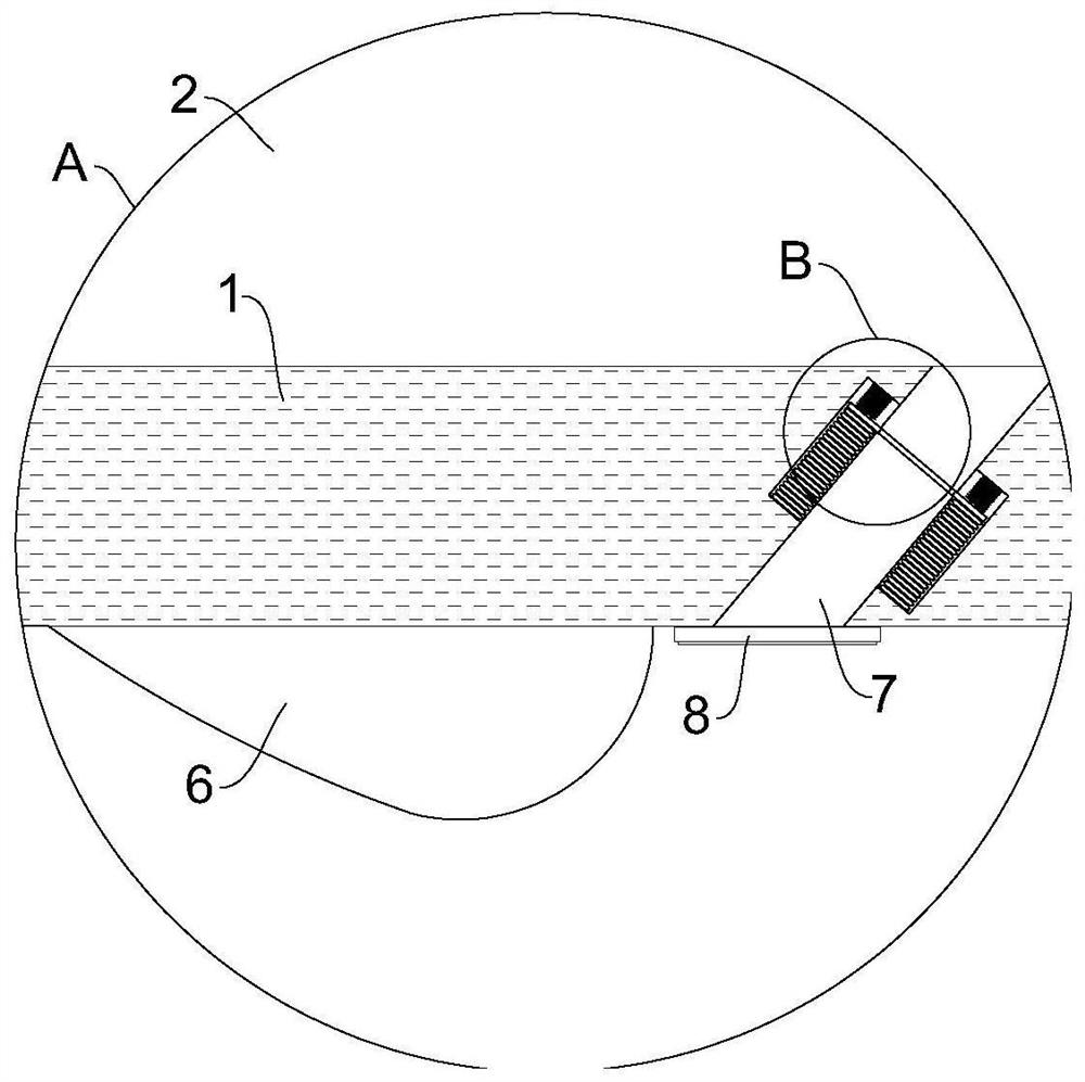
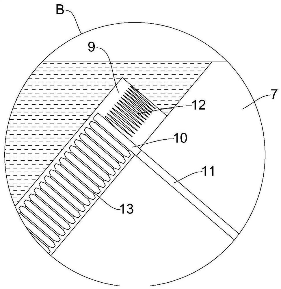
The invention relates to the technical field of wind power generation, in particular to a wind turbine blade and a wind turbine generator. The wind turbine blade comprises a shell, a device cavity is formed in the shell, a power generation equipment body is fixedly installed in the device cavity, a rotating shaft is rotatably installed in the power generation equipment body, the front end of the rotating shaft penetrates through the side wall of the device cavity and extends out of the shell, and a plurality of fan blades are fixedly installed at the position, outside the shell, of the front end of the rotating shaft. Air flow is fed into an air inlet and discharged from an air outlet in the rear end of the device cavity, then the power generation equipment body in the device cavity is rapidly cooled, dust and impurities in the air flow are filtered, and the situation that normal work of the power generation equipment body is affected due to dust accumulation in the device cavity is avoided; and then air is sprayed to a filter plate through a plurality of spray heads, then accumulated dust in the filter plate is sprayed away, and the situation that equipment in the device cavity is damaged due to long-time high temperature can be avoided.

Description

technical field [0001] The invention relates to the technical field of wind power generation, in particular to a wind turbine blade and a wind turbine generator. Background technique [0002] A wind turbine, also known as a wind energy converter, is a device that converts the kinetic energy of the wind into electrical energy. The working principle of a wind generator is relatively simple. The wind wheel rotates under the action of the wind, which converts the kinetic energy of the wind into wind Driven by the mechanical energy of the wheel shaft, the generator rotates to generate electricity. In a broad sense, wind energy is also solar energy, so it can also be said that a wind generator is a thermal energy utilization generator that uses the sun as a heat source and the atmosphere as a working medium. [0003] Existing patent (notification number: CN111911367A) a wind turbine generator, including a main body of protective equipment, the outer surface of the lower end of th...

Claims


Application Information

Patent Timeline
Patent Type & Authority Applications(China)
IPC IPC(8): F03D1/06F03D80/00F03D80/55F03D80/60G08B21/24A01M29/08
CPCF03D1/0675F03D1/0633F03D80/00F03D80/60F03D80/55A01M29/08G08B21/24Y02E10/72
Inventor 黎阜南张昊森刘子豪
Owner 黎阜南
Learn More