3D laser radar and foot type robot

A laser radar and 3D technology, applied in the direction of instruments, manipulators, radio wave measurement systems, etc., can solve the problems of inability to realize high-frequency scanning, high sensor requirements, and unfavorable promotion and use, so as to facilitate the promotion and use, wide application range, The practical effect of the plan

Pending Publication Date: 2022-01-21
HZ UNITREE TECHNOLOGY CO LTD
View PDF1 Cites 7 Cited by
  • Summary
  • Abstract
  • Description
  • Claims
  • Application Information

AI Technical Summary

Problems solved by technology

[0006] In the above solution, the drive motor directly drives the lidar sensor to scan in the vertical direction through the gear, but the structure of the lidar sensor is relatively precise and complex. For some high-frequency applications, the vertical scanning frequency needs to be very high, and its rotation life must be considered , connection strength, dynamic balance, moment of inertia and many other factors, the structure is relatively complex, and the requirements for existing lidar sensors are very high, resulting in high manufacturing costs
[0007] Furthermore, the above scheme drives the lidar sensor to rotate through the gear, but the scanning frequency is very low through the gear to drive the sensor to rotate, and high-frequency scanning cannot be realized, and the scope of application is narrow, which is not conducive to popularization and use.

Method used


Image

  • 3D laser radar and foot type robot
  • 3D laser radar and foot type robot
  • 3D laser radar and foot type robot

Examples


specific Embodiment

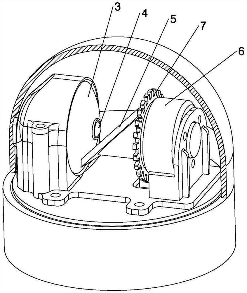
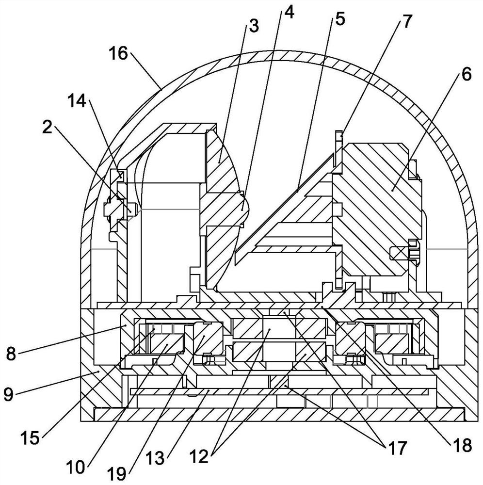
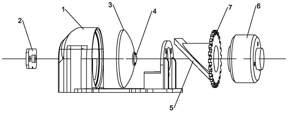
[0043] The vertical scanning unit also includes a first motor 6 and a first code wheel 7, the first motor 6 drives the reflector 5 to rotate, the first code wheel 7 is fixedly connected concentrically with the reflector 5, The rotation information of the reflector 5 is obtained through the first code wheel 7 .

[0044] A cooling fan is fixed coaxially with the first code wheel 7 on the output shaft of the first motor 6 . This structure is used for the airflow circulation inside the lidar, which is beneficial to the heat dissipation of heat-generating components such as motors. The structure is simple and the cost is low.

[0045] The present invention directly drives the reflector 5 to rotate at high speed through the first motor 6, so that the present invention can realize high-frequency scanning without affecting high-precision components such as the laser emitter 4. The scheme is simple and feasible.

[0046] A specific embodiment in which the visible light emitter 14 is ...


PUM


Abstract

The invention relates to the technical field of laser radar equipment, and discloses a 3D laser radar and a foot type robot. The 3D laser radar provided by the invention comprises a vertical scanning unit and a horizontal rotating device; the vertical scanning unit comprises a mounting base, and a laser receiving electrode, a convex lens, a laser emitting electrode and a reflecting body which are sequentially arranged on the mounting base; the laser receiving electrode is arranged at the focus position of the convex lens, the laser emitting electrode is arranged on the main optical axis of the convex lens, and the reflecting body is rotatably arranged on the mounting base; the rotation center of the reflector coincides with the main optical axis of the convex lens; and a laser pulse signal realizes environment scanning in a vertical plane through rotation of the reflector, and further realizes scanning of a three-dimensional environment through the horizontal rotating device. Two-dimensional scanning in a vertical plane in the environment is achieved through the vertical scanning unit, the vertical scanning unit is rotated in the horizontal direction through the horizontal rotating device, and three-dimensional scanning of the surrounding environment is achieved.

Description

technical field [0001] The invention relates to the technical field of laser radar equipment, in particular to a 3D laser radar and a legged robot. Background technique [0002] At present, lidar is widely used in industrial surveying and mapping, 3D modeling, autonomous driving and other fields. For example, in the application scenario of automatic follow, the mobile device emits a laser beam to the detected object around it, and then receives the light signal reflected by the detected object, and after processing, obtains the position information of the detected object around the mobile device. [0003] However, most of the existing laser radars are two-dimensional laser radars, or although they can scan the three-dimensional environment, the scanning blind area is large, the scanning angle of a single radar is small, and the surrounding environment information is obtained. Large scanning viewing angle, and the use of multiple sets of laser transceiver components, the cos...

Claims


Application Information

Patent Timeline
Patent Type & Authority Applications(China)
IPC IPC(8): G01S7/481B25J11/00
CPCG01S7/4817B25J11/00
Inventor 王兴兴白晓阳
Owner HZ UNITREE TECHNOLOGY CO LTD
Why Eureka
Try Eureka