
Intelligent monitoring and alarming system

An alarm system and intelligent monitoring technology, applied in the direction of alarms, closed-circuit television systems, electrical transmission signal systems, etc., can solve the problems of troublesome maintenance of alarm devices, inability to send out alarm sounds quickly and continuously, and achieve convenient maintenance and installation. Effect

Inactive Publication Date: 2022-01-21
汪文华
View PDF1 Cites 0 Cited by
  • Summary
  • Abstract
  • Description
  • Claims
  • Application Information

AI Technical Summary

Problems solved by technology

[0004] There is an alarm sound that cannot be issued quickly and continuously, which is very troublesome for the maintenance of the alarm device, and needs to be improved

Method used


Image

  • Intelligent monitoring and alarming system
  • Intelligent monitoring and alarming system
  • Intelligent monitoring and alarming system

Examples


Embodiment 1

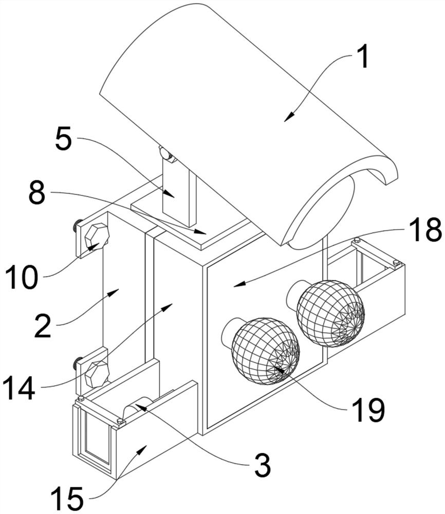
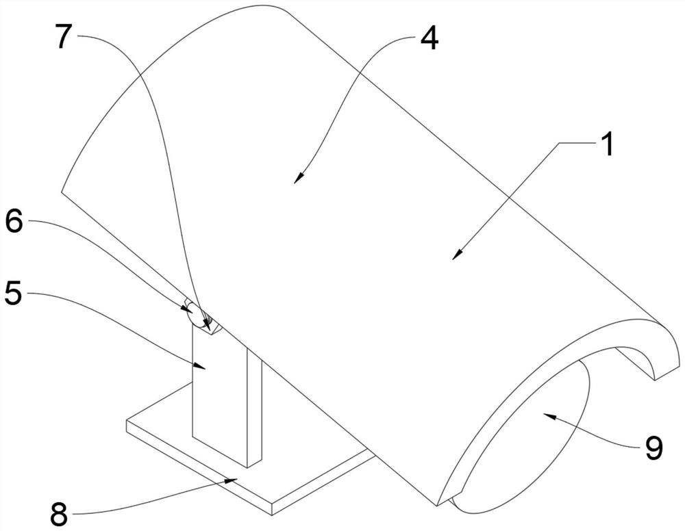
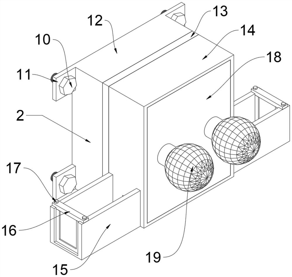
[0028] An intelligent monitoring and alarm system, such as figure 1 As shown, it includes a monitoring device 1, the lower end surface of the monitoring device 1 is fixedly connected with a fixing device 2, and an alarm device 3 is installed inside the fixing device 2, as shown in Figure 2, the monitoring device 1 includes a protective shell 4, a pillar 5, a screw thread Column 6, nut 7, chassis 8 and camera 9, chassis 8 is located at the bottom of monitoring device 1, and pillar 5 is symmetrically fixedly connected to the upper end surface of chassis 8, and threaded column 6 is all rotatably connected to the upper end of pillar 5, and camera 9 is fixedly connected On the inner end face of the pillar 5, the nut 7 is all screwed to one end of the threaded pillar 6, and the protective shell 4 is fixedly connected to the upper end of the camera 9, such as image 3 , 4, 5, 6, and 7, the fixing device 2 includes a first fixing screw 10, a first positioning block 11, a fixing frame...

Embodiment 2

[0032] On the basis of Example 1, such as Figure 9 , 10 As shown, the fixing device 2 also includes a handle 41, a clamping strip 42, a clamping plate 43, a second positioning block 44, a first rotating shaft 45 and a second rotating shaft 46, the handle 41 is fixedly connected to the middle part of the upper end of the baffle plate 18, and the clamping plate 43 is fixedly connected to the top of the baffle 18, the second positioning block 44 is symmetrically fixedly connected to the upper end of the baffle 18, the first rotating shaft 45 is symmetrically rotatably connected to the front end of the outer frame 14, and the clamping strip 42 is fixedly connected to the first The upper end surface of the rotating shaft 45 and the second rotating shaft 46 are symmetrically and fixedly connected to the lower end of the baffle 18 , and the baffle 18 is rotatably connected to the outer frame 14 through the second rotating shaft 46 .

[0033] When this embodiment is in use, the firs...


PUM


Abstract

The invention discloses an intelligent monitoring and alarming system, and the system comprises a monitoring device and is characterized in that the lower end face of the monitoring device is fixedly connected with a fixing device, and an alarming device is installed in the fixing device; the monitoring device comprises a protective shell, a supporting column, a threaded column, a nut, a chassis and a camera; the fixing device further comprises a handle, a clamping strip, a clamping plate, second positioning blocks, first rotating shafts and second rotating shafts; the handle is fixedly connected to the middle of the upper end of the baffle, the clamping plate is fixedly connected to the top end of the baffle, the second positioning blocks are symmetrically and fixedly connected to the upper end of the baffle, and the first rotating shafts are symmetrically and rotationally connected to the upper end of the front end face of the outer frame; the clamping strip is fixedly connected to the upper end faces of the first rotating shafts, the second rotating shafts are symmetrically and fixedly connected to the lower end of the baffle, and the baffle is rotationally connected with the outer frame through the second rotating shafts.

Description

technical field [0001] The invention relates to the field of intelligent security technology, in particular to an intelligent monitoring and alarm system. Background technique [0002] According to Chinese Patent No. CN201622657U, the present invention provides an intelligent monitoring and alarm device, which includes a microprocessor circuit module, a GPS positioning module, an alarm platform, a fingerprint collection module, an audio collection module, a video collection module, a transmission module, an owner The mobile phone and the receiving module, the GPS positioning module, the fingerprint collection module, the audio collection module, the video collection module, the transmitting module, and the receiving module are respectively connected to the microprocessor circuit module, and the The owner's mobile phone communicates with the transmitting module and the receiving module respectively through the GSM network, and the alarm receiving platform communicates with th...

Claims


Application Information

Patent Timeline
IPC IPC(8): H04N7/18H04N5/225H04N5/232G08B21/24G08B7/06G08B7/02F16M11/10F16M13/02
CPCH04N7/18G08B21/24G08B7/06G08B7/02F16M11/10F16M13/02H04N23/51H04N23/50H04N23/695
Inventor 不公告发明人
Owner 汪文华
Learn More