Eureka AIR delivers breakthrough ideas for toughest innovation challenges, trusted by R&D personnel around the world.

Paper bag flat rope externally-attached handle conveying device

A technology of conveying device and sticking handle, applied in the directions of transportation and packaging, packaging, papermaking, etc., can solve the problems of reducing paper cost and production cost, unstable finger claws biting the flat rope, affecting the stable work of the machine, etc., to avoid flattening. Rope jamming, reliable conveying, reliable effect of action execution

Pending Publication Date: 2022-01-25
上豪包装机械(镇江)有限公司
View PDF0 Cites 0 Cited by
  • Summary
  • Abstract
  • Description
  • Claims
  • Application Information

AI Technical Summary

Problems solved by technology

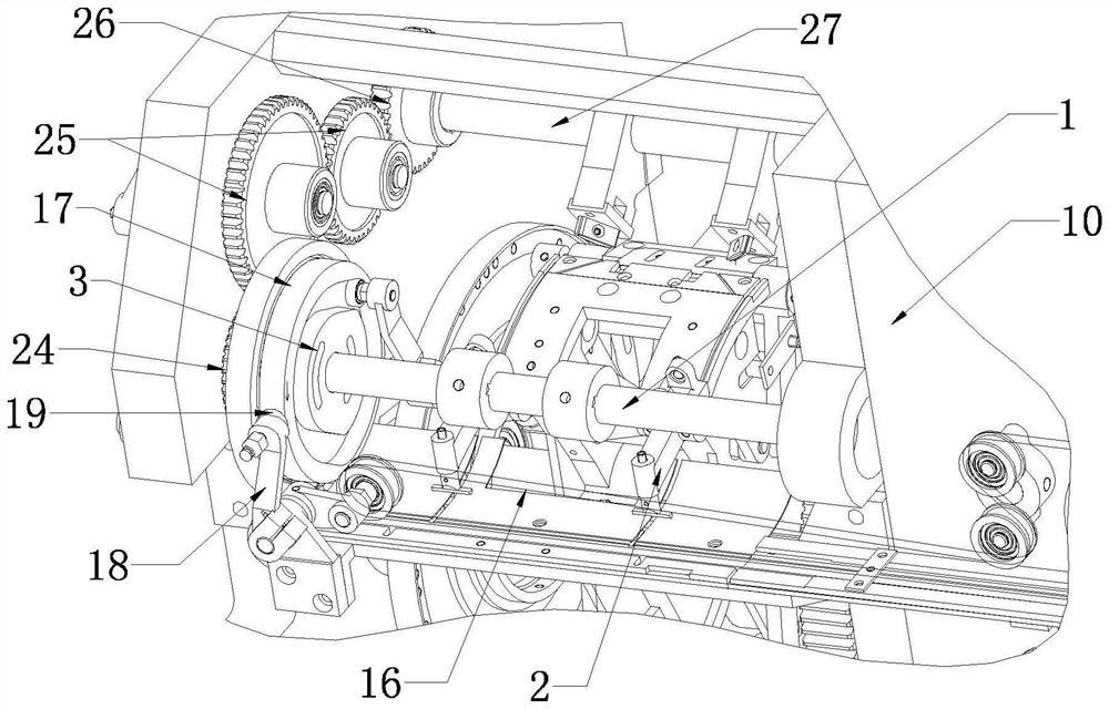
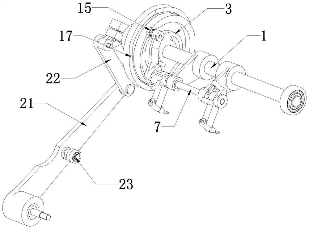
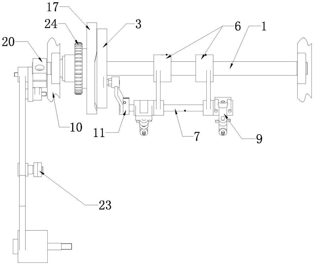
[0002] Paper bags are used more and more widely. For paper bag handles, since the handle of the flat rope has no handle piece, the flat rope is directly pasted on the outside of the paper bag with glue, thereby reducing the cost of paper and production, which also makes the paper bag stick flat on the outside. The application of rope handles is more popular, and the number of markets has increased sharply. In the prior art, in order to improve the manufacturing efficiency, the flat rope handles need to be grasped one by one by fingers and claws during the production process and then transported to the handle manufacturing place. However, due to the The width is very narrow, therefore, it is easy to miss the problem when using fingers and claws to occlude. In addition, the flat rope is transported to the handle by the belt. The rope is unstable, and it is easy to cause the flat rope to be not conveyed in place and the flat rope to be blocked, which will affect the stable operation of the machine

Method used


Image

  • Paper bag flat rope externally-attached handle conveying device
  • Paper bag flat rope externally-attached handle conveying device
  • Paper bag flat rope externally-attached handle conveying device

Examples


Embodiment Construction

[0026] In the following, the conveying device for attaching the handle of the paper bag flat rope to the outside of the present invention will be further described in detail in conjunction with the accompanying drawings and specific embodiments.

[0027] As shown in the figure, the paper bag flat rope external handle conveying device of the present invention includes two left and right wall panels 10, a main shaft 1 installed between the left and right two wall panels 10 through bearings, and a pin insertion mechanism 2 fixedly installed on the main shaft , the main shaft 1 is covered with a pin swing device 3 for driving the swing of the pin mechanism, which is composed of figure 2 , image 3 , Image 6 It can be seen that the pin insertion mechanism 2 includes a pair of fixed bases 6 with mounting sleeves 5 fixedly installed on the main shaft 1, a connecting shaft 7 installed through two mounting sleeves, and two connecting shafts with insertion sleeves installed on the co...


PUM


Abstract

The invention discloses a paper bag flat rope externally-attached handle conveying device. The paper bag flat rope externally-attached handle conveying device comprises a main shaft which is supported and installed through a wall plate, and a pin mechanism which is fixedly installed on the main shaft, wherein the main shaft is sleeved with a pin swinging device used for driving the pin mechanism to swing in an empty mode; the pin mechanism and the pin swinging device are installed in a matched mode and can be driven by the pin swinging device to swing to the position where a flat rope handle is located; the wall plate is further provided with an angle adjusting mechanism used for adjusting the swing angle of the pin mechanism; and the angle adjusting mechanism is connected with the main shaft through a connecting rod mechanism and can drive the main shaft to rotate through the connecting rod mechanism under driving of the angle adjusting mechanism, so that a pin on the pin mechanism can directly face the flat rope handle. The paper bag flat rope externally-attached handle conveying device has the advantages that through the structural design, the pin mechanism is used for conveying the flat rope handle, so that the grabbing missing problem is effectively avoided, the grabbing position is accurate, and it is guaranteed that the flat rope handle can be conveyed accurately and stably.

Description

technical field [0001] The invention relates to a conveying mechanism in packaging bag making equipment, in particular to a conveying device with a handle attached to the outside of a paper bag flat rope. Background technique [0002] Paper bags are used more and more widely. For paper bag handles, since the handle of the flat rope has no handle piece, the flat rope is directly pasted on the outside of the paper bag with glue, thereby reducing the cost of paper and production, which also makes the paper bag stick flat on the outside. The application of rope handles is more popular, and the number of markets has increased sharply. In the prior art, in order to improve the manufacturing efficiency, the flat rope handles need to be grasped one by one by fingers and claws during the production process and then transported to the handle production place. However, due to the The width is very narrow, therefore, it is easy to miss the problem when using fingers and claws to occlude...

Claims


Application Information

Patent Timeline
Patent Type & Authority Applications(China)
IPC IPC(8): B31B70/86B31B70/04
CPCB31B70/864B31B70/04
Inventor 朱东
Owner 上豪包装机械(镇江)有限公司
Why Eureka
Eureka Blog
Learn More