
Small gas turbine rack

A gas turbine and bench technology, which is applied to gas turbine devices, mechanical equipment, jet propulsion devices, etc., can solve the problems of difficulty in realizing free adjustment of horizontal position, reducing the installation efficiency of gas turbines, and inconvenient centering work, and the installation method is simple and fast. , The effect of convenient operation and convenient transportation

Pending Publication Date: 2022-01-25
上海持承自动化设备有限公司
View PDF0 Cites 0 Cited by
  • Summary
  • Abstract
  • Description
  • Claims
  • Application Information

AI Technical Summary

Problems solved by technology

[0003] Couplings are used to connect the gas turbine to the torquer and the reducer to the dynamometer. When the output shaft of the gas turbine is connected to the input shaft of the torquer, the center positions of the two shafts are not on the same straight line, and frequent disassembly is usually required The centering work of the gas turbine, the traditional gas turbine bench is usually fixed, it is difficult to realize the free adjustment of the horizontal position, which brings a lot of inconvenience to the centering work, not only time-consuming and laborious but also reduces the installation efficiency of the gas turbine, in view of the above problems, this paper The invention provides a small gas turbine bench

Method used


Image

  • Small gas turbine rack
  • Small gas turbine rack
  • Small gas turbine rack

Examples


Embodiment Construction

[0023] The following will clearly and completely describe the technical solutions in the embodiments of the present invention with reference to the accompanying drawings in the embodiments of the present invention. Obviously, the described embodiments are only some, not all, embodiments of the present invention.

[0024] see Figure 1 to Figure 4 :

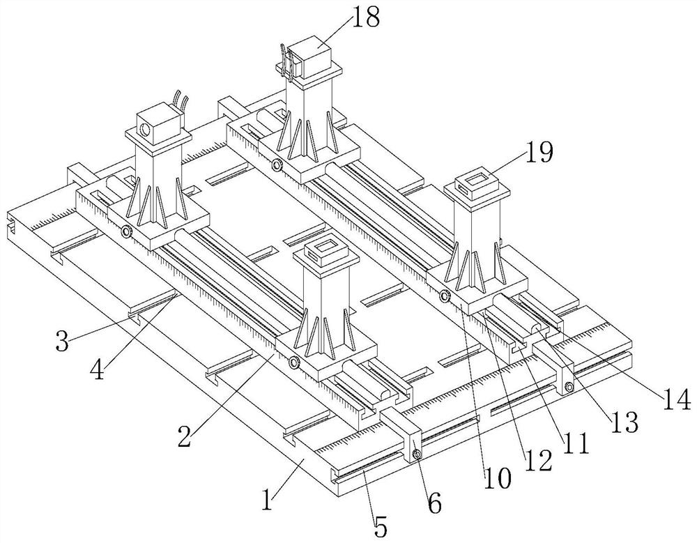
[0025] A small gas turbine stand, including a base 1, an adjustment plate 2 and an adjustment block 10;

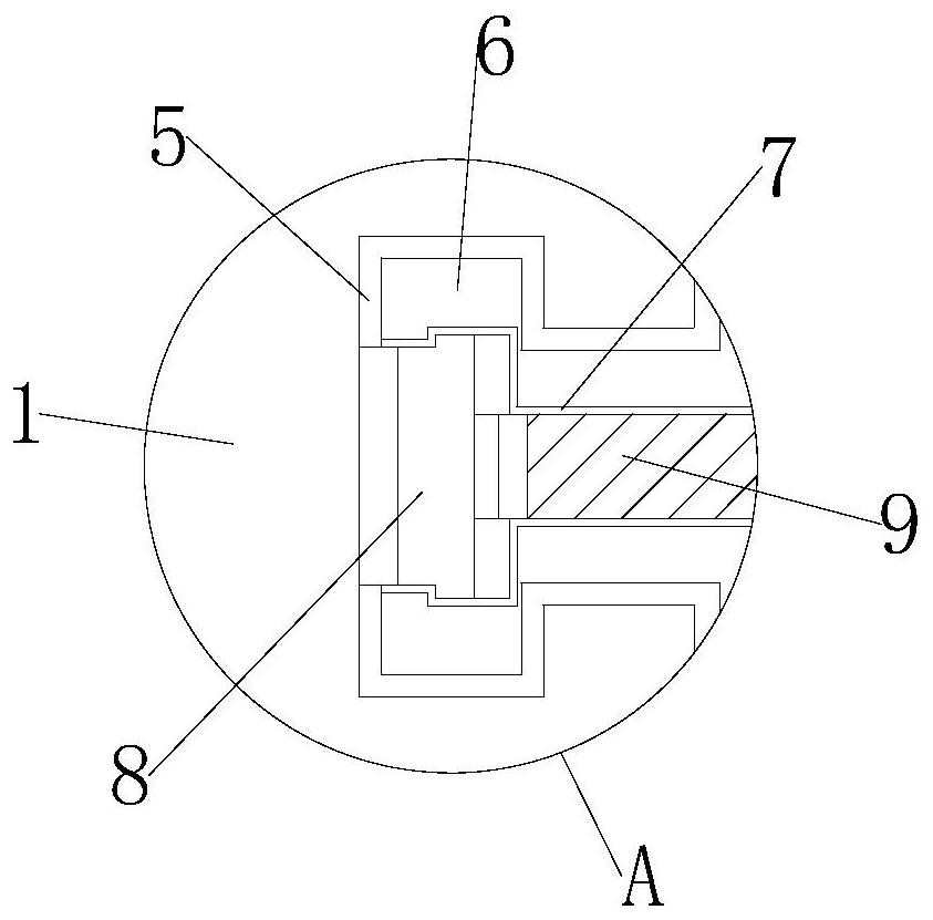
[0026] Adjusting plate 2 is provided with two pieces, and two adjusting plates 2 are symmetrically arranged on the front and rear sides above the base 1, and the front and rear ends of the left and right sides of the base 1 are all provided with chute 3 5, and the left and right ends of the adjusting plate 2 are fixed with The sliding frame 6 connected by the chute three 5, the outer side of the sliding frame 6 is penetrated with a groove one 7, the inner end of the groove one 7 is provided with a top block one 8, and the out...


PUM


Abstract

The invention relates to the technical field of gas turbines, in particular to a small gas turbine rack. The small gas turbine rack comprises a base, two adjusting plates and adjusting blocks, the two adjusting plates are symmetrically arranged on the front side and the rear side of the upper portion of the base, third sliding grooves are formed in the front ends and the rear ends of the left side and the right side of the base correspondingly, sliding frames slidably connected with the third sliding grooves are fixed to the left ends and the right ends of the adjusting plates correspondingly, first grooves are formed in the outer sides of the sliding frames in a penetrating mode, first ejector blocks are arranged at the inner ends of the interiors of the first grooves, first screw rods are rotationally connected to the outer sides of the first ejector blocks, the four adjusting blocks are evenly arranged above the two adjusting plates in a pairwise left-right arrangement mode, a protruding strip is welded to the middle of the upper portion of each adjusting plate, a strip-shaped groove connected with the protruding strip in a sliding mode is formed in the lower portion of each adjusting block, second grooves communicating with the strip-shaped grooves are formed in the front ends of the adjusting blocks, second ejector blocks are arranged at the rear ends inside the second grooves, and second screw rods are rotationally connected to the front ends of the second ejector blocks. The small gas turbine rack has the beneficial effects that the self-aligning work is facilitated, and the mounting efficiency is improved.

Description

technical field [0001] The invention relates to the technical field of gas turbines, in particular to a small gas turbine stand. Background technique [0002] The gas turbine is an internal combustion power machine that uses continuous flowing gas as the working medium to drive the impeller to rotate at high speed, and converts the energy of the fuel into useful work. It is a rotary impeller heat engine. [0003] Couplings are used to connect the gas turbine to the torquer and the reducer to the dynamometer. When the output shaft of the gas turbine is connected to the input shaft of the torquer, the center positions of the two shafts are not on the same straight line, and frequent disassembly is usually required The centering work of the gas turbine, the traditional gas turbine stand is usually fixed, it is difficult to realize the free adjustment of the horizontal position, which brings a lot of inconvenience to the centering work, not only time-consuming and laborious but ...

Claims


Application Information

Patent Timeline
Patent Type & Authority Applications(China)
IPC IPC(8): F02C7/20
CPCF02C7/20
Inventor 林盛华
Owner 上海持承自动化设备有限公司
Learn More