Automatic lamination equipment for silicon steel sheets

A silicon steel sheet and lamination technology, which is applied in the field of automatic silicon steel sheet lamination equipment, can solve the problems that it is impossible to distinguish whether the silicon steel sheet is offset, the requirements for automatic lamination equipment are high, and it is difficult to see the silicon steel sheet. Effects of using a driving source, reducing offset, and reducing equipment cost

Pending Publication Date: 2022-01-25
芜湖森普铁芯有限公司
View PDF1 Cites 1 Cited by
  • Summary
  • Abstract
  • Description
  • Claims
  • Application Information

AI Technical Summary

Problems solved by technology

[0005] 1. Although this solution discloses a simple lamination method, when lamination is carried out in this way, layer-by-layer lamination is often required, and layer-by-layer lamination requires high requirements for automatic lamination equipment , therefore, using this method often requires workers to perform lamination
[0006] 2. The usual lamination equipment is to laminate silicon steel sheets in a single sheet. During

Method used


Image

  • Automatic lamination equipment for silicon steel sheets
  • Automatic lamination equipment for silicon steel sheets
  • Automatic lamination equipment for silicon steel sheets

Examples


Embodiment Construction

[0044] The technical solutions of the present invention will be further described below in conjunction with the accompanying drawings and through specific implementation methods.

[0045] Wherein, the accompanying drawings are only for illustrative purposes, showing only schematic diagrams, rather than physical drawings, and should not be construed as limitations on this patent; in order to better illustrate the embodiments of the present invention, some parts of the accompanying drawings will be omitted, Enlarged or reduced, does not represent actual product size.

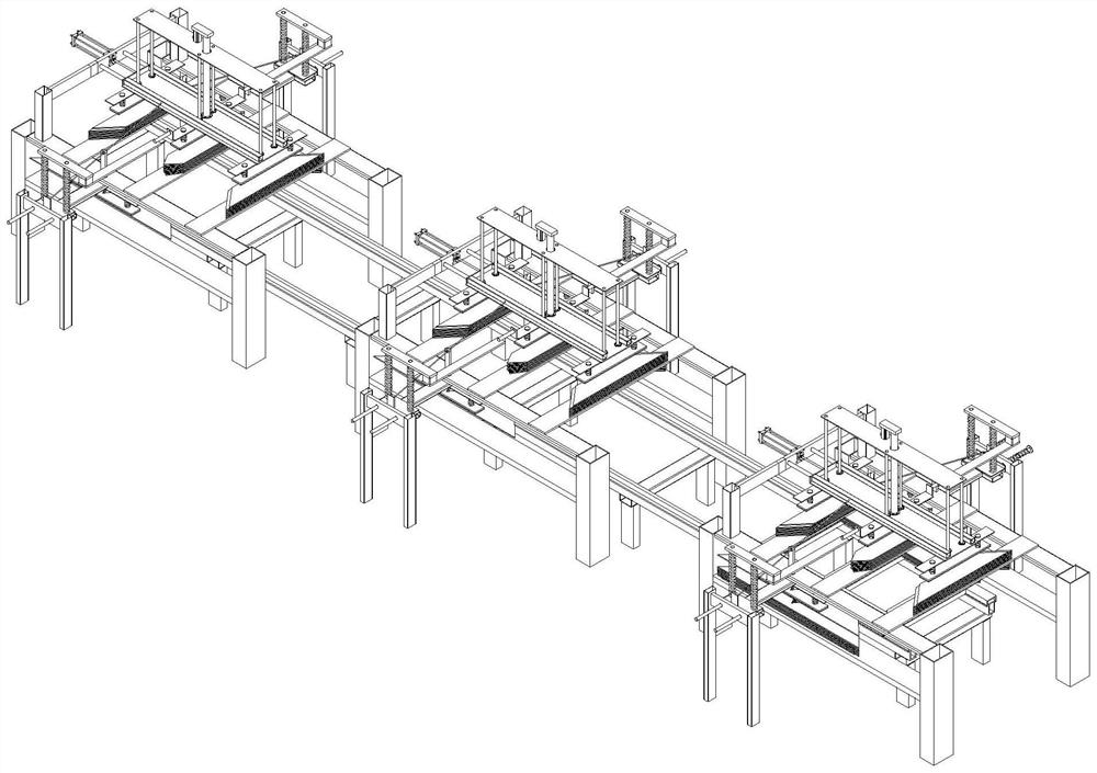
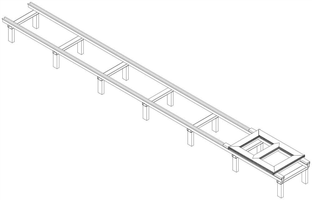
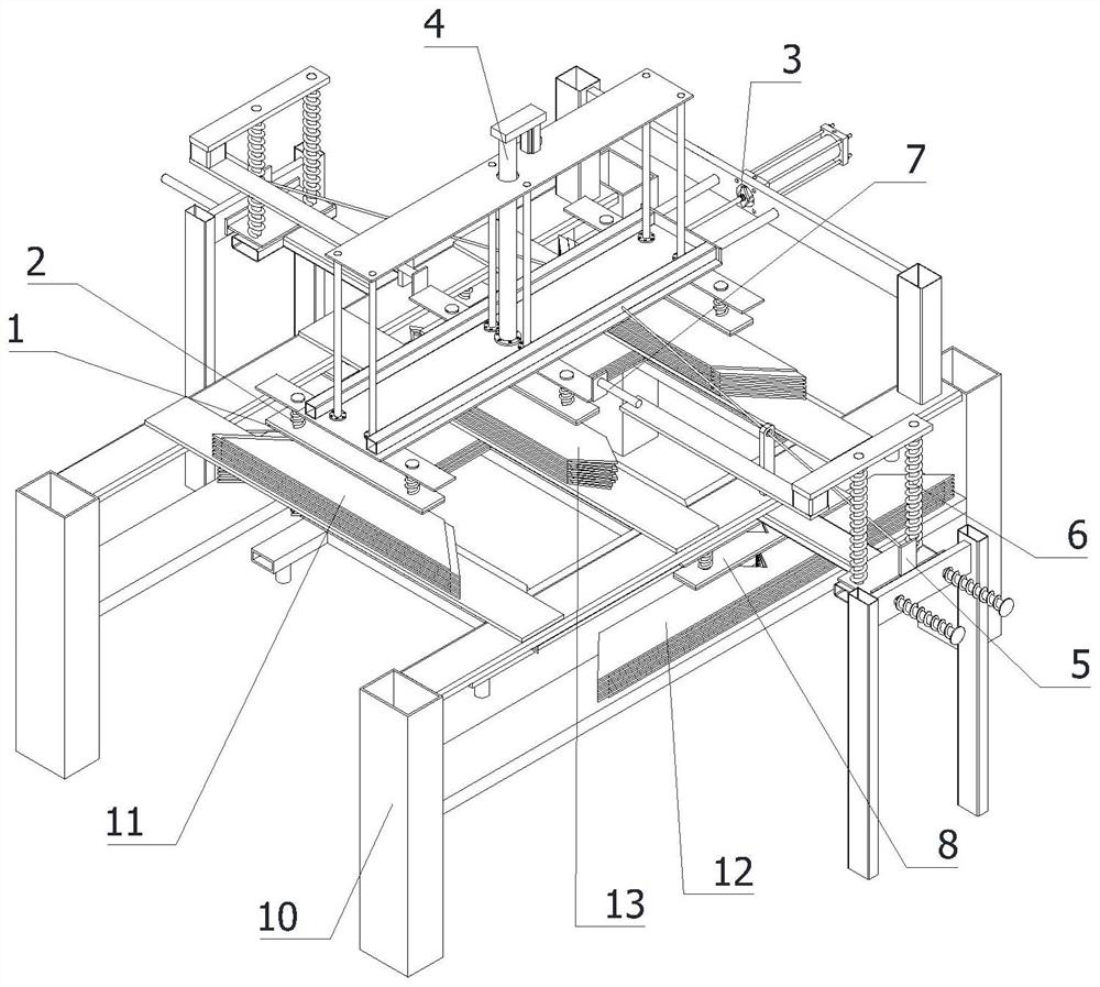
[0046] refer to Figure 1 to Figure 11 The automatic lamination equipment for silicon steel sheets shown includes a sliding frame, a mounting base and several single-layer disk drives. The sliding frame is fixedly installed on the ground, and the mounting base can be detachably installed on the sliding frame. A single-layer disk drive is evenly distributed along the sliding frame;

[0047] Each single-layer disc...


PUM


Abstract

The invention relates to the field of silicon steel sheet lamination, in particular to automatic lamination equipment for silicon steel sheets. The equipment comprises a sliding frame, a mounting seat and a plurality of single-layer disc machines, and each single-layer disc machine comprises a stacking frame, a transverse pulling mechanism, a pressing mechanism, two synchronous pulling mechanisms, a double-layer synchronous pressing mechanism, a transmission connector, a second elastic mounting seat, three first elastic mounting seats and five electromagnets. The double-layer synchronous pressing mechanism can be automatically separated from the transmission connector through a transmission plate, a driving source is prevented from being used for separation, and the equipment cost is reduced. The transmission pipe is driven by the transmission connector to move, the driving source is reduced, and the equipment cost is reduced. The transmission pipe is driven to descend when the transmission connector descends, a middle silicon steel sheet, two longitudinal silicon steel sheets and a transverse silicon steel sheet descend at the same time, the observation time of workers is prolonged, and the risk of silicon steel sheet deviation is reduced.

Description

technical field [0001] The invention relates to the field of lamination of silicon steel sheets, in particular to an automatic lamination equipment of silicon steel sheets. Background technique [0002] When laminating silicon steel sheets, workers are often used for positioning and installation, and positioning and installation by workers often consumes a lot of time for workers. There will be no offset during the stacking of silicon steel sheets, and the stacking is done through equipment. Due to the high cost of conventional lamination equipment, often small-scale manufacturers can only use workers to stack. [0003] my country's patent application number: CN201610798906.1; discloses the silicon steel sheet unit of the transformer core and the assembly method of the transformer. The invention can make the stacking of the silicon steel sheets of the silicon steel sheet unit more simple and convenient, thereby improving the stacking of the silicon steel sheet. Moreover, it ...

Claims


Application Information

Patent Timeline
IPC IPC(8): H01F41/02
CPCH01F41/0233
Inventor 姚强廖富周卢小俭
Owner 芜湖森普铁芯有限公司
Why Eureka
Try Eureka