
Cooling device for IC engine

A technology of cooling device and internal combustion engine, which is applied in the direction of engine cooling, liquid cooling, and coolant flow control, etc., can solve the problems of reducing the effect of knocking cylinders and not considering the cooling of the cylinder head, etc., so as to improve the fuel utilization rate and realize the early warm-up period. machine, reduce the effect of knocking the cylinder

Inactive Publication Date: 2004-02-25
HONDA MOTOR CO LTD
View PDF1 Cites 0 Cited by
  • Summary
  • Abstract
  • Description
  • Claims
  • Application Information

AI Technical Summary

Problems solved by technology

However, the cooling of the cylinder head in the area where knocking occurs is not considered, so the effect of reducing knocking cannot be obtained

Method used


Image

  • Cooling device for IC engine
  • Cooling device for IC engine
  • Cooling device for IC engine

Examples


Embodiment Construction

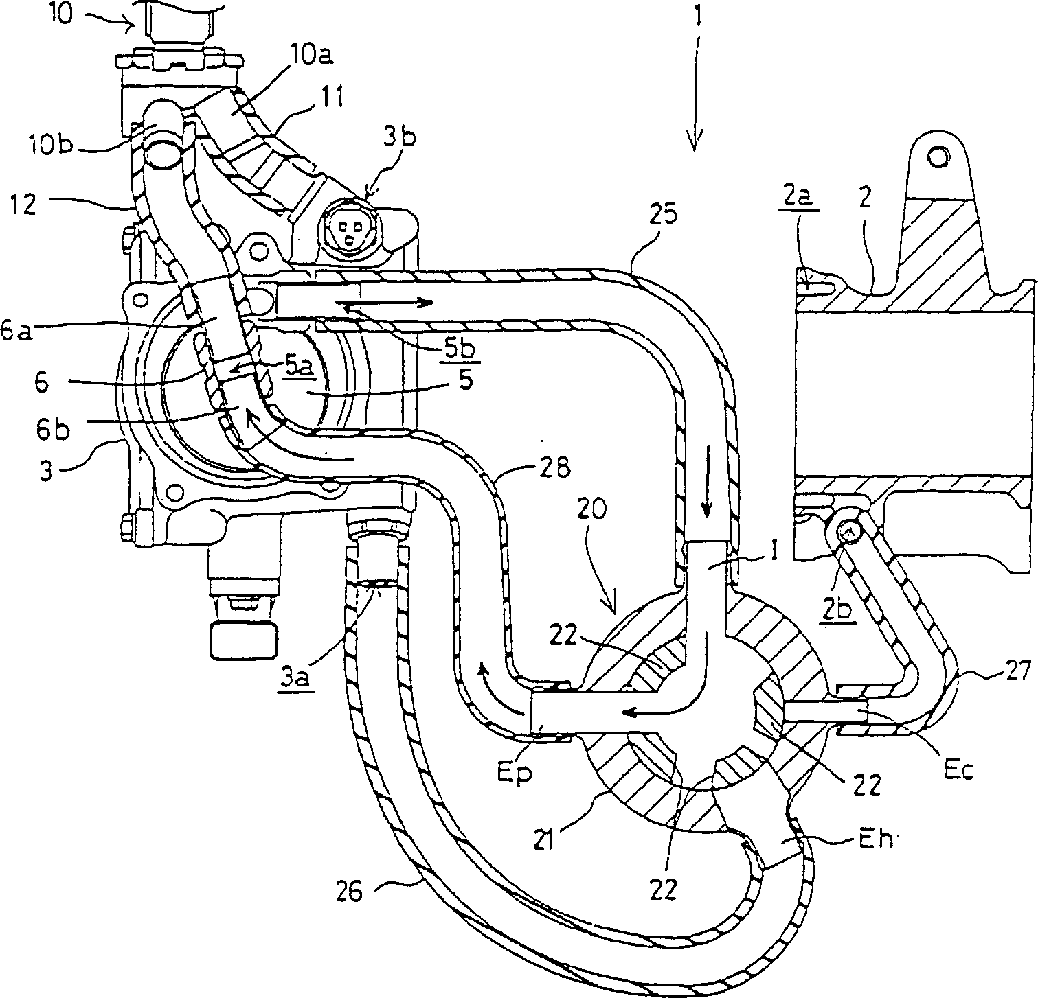
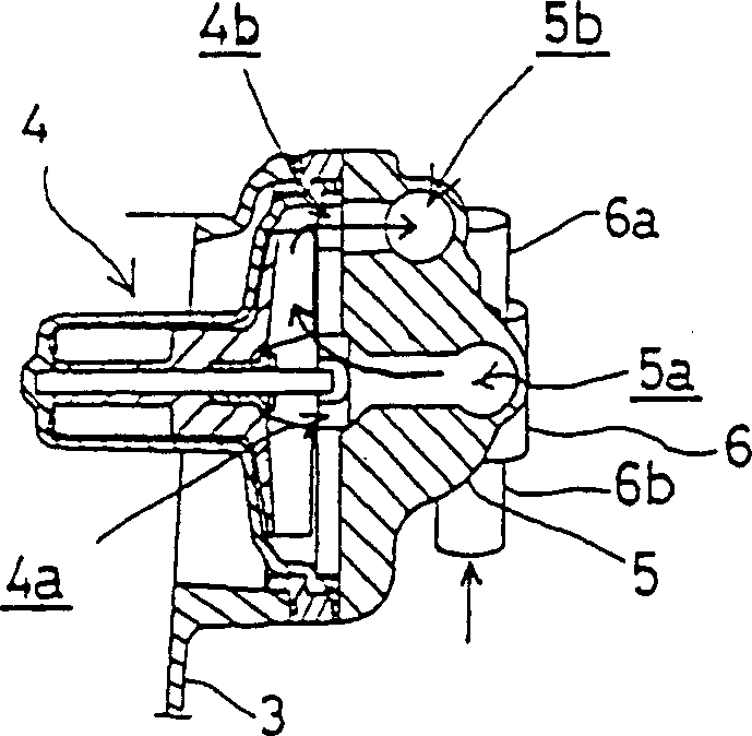
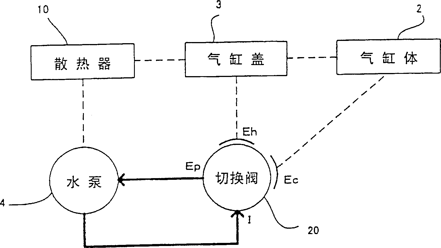
[0049] Below, refer to Figure 1 to Figure 9 , to illustrate an embodiment of the present invention.

[0050] Figure 1 to Figure 3 Shows the state at the time of cold start in the cooling structure of the internal combustion engine 1 of the present embodiment, Figure 4 and Figure 5 Indicates the state during normal driving, Image 6 and Figure 7 Indicates the state during acceleration.

[0051] refer to figure 1 and figure 2 , illustrating the cooling configuration.

[0052] The cylinder block 2 and the cylinder head 3 of the internal combustion engine 1 are shown as separated in the drawings, but they are actually integrated by a gasket. The water jacket 2a around the cylinder bore of the cylinder block 2 communicates with the water jacket around the combustion chamber of the cylinder head 3 through the gasket hole.

[0053] The cylinder block 2 has a cooling water inlet 2b communicating with the water jacket 2a, and the cylinder head 3 has a cooling water inlet...


PUM


Abstract

To provide a cooling device for an internal combustion engine capable of controlling switch to supply of cooling water to a cylinder and a cylinder head based on a throttle opening and thereby reduce knocking and improve fuel consumption. The characteristic is in that it is provided with an engine rotational frequency sensor 32 for detecting an engine rotational frequency of the internal combustion engine, a throttle sensor 33 for detecting an opening of a throttle valve, a switch valve 20 for optionally switching to supply the cooling water to the cylinder or the cylinder head of the internal combustion engine, a driving means 31 for driving the switch valve 20, and a control means 30 for controlling the driving means 31 based on the throttle opening theta Th detected by the throttle sensor 33 and the engine rotational frequency Ne detected by the engine rotational frequency sensor 32. The control means 30 drives the driving means 31 to supply the cooling water to the cylinder head when it is determined that the throttle opening the engine rotating speed is large compared to the throttle opening.

Description

technical field [0001] The invention relates to a cooling device in a water-cooled internal combustion engine. Background technique [0002] Usually, in a water-cooled internal combustion engine, the water jacket on the cylinder block side and the water jacket on the cylinder head side are connected, and the cooling water discharged from the water pump flows from the cylinder to the cylinder head, and cools the engine after circulating in the radiator. [0003] Therefore, the amount of water corresponding to the engine speed and operating load cannot be supplied to the cylinder and the cylinder head. [0004] In this way, the cooling of the cylinder head is slow, which is likely to cause knocking, or because the internal combustion engine is cooled from the cylinder, the thermal efficiency decreases, resulting in a decrease in fuel efficiency. [0005] In addition, JP 2000-73770 A discloses an example in which the cylinder and the cylinder head are piped separately, and the...

Claims


Application Information

Patent Timeline
Patent Type & Authority Patents(China)
IPC IPC(8): F01P7/16F01P3/02
Inventor 阿部德男
Owner HONDA MOTOR CO LTD
Learn More