Eureka AIR delivers breakthrough ideas for toughest innovation challenges, trusted by R&D personnel around the world.

Delay-free control method and control device for high-speed brushless direct current motor

A brush DC motor, delay control technology, applied in the direction of electronic commutation motor control, single motor speed/torque control, control system, etc., can solve the problems of motor commutation delay, motor efficiency reduction, etc., to achieve easy implementation, method scientific effect

Pending Publication Date: 2022-01-25
JIANGSU UNIV OF SCI & TECH
View PDF1 Cites 0 Cited by
  • Summary
  • Abstract
  • Description
  • Claims
  • Application Information

AI Technical Summary

Problems solved by technology

[0004] In order to solve the problems of motor commutation delay and motor efficiency reduction caused by traditional filtering methods, this invention designs a window filter with controllable delay time according to the characteristics of interference signals, and proposes a commutation method without filter delay

Method used


Image

  • Delay-free control method and control device for high-speed brushless direct current motor
  • Delay-free control method and control device for high-speed brushless direct current motor
  • Delay-free control method and control device for high-speed brushless direct current motor

Examples


Embodiment Construction

[0035] Embodiments of the present invention will be disclosed in the following diagrams. For the sake of clarity, many practical details will be described together in the following description. It should be understood, however, that these practical details should not be used to limit the invention. That is, in some embodiments of the invention, these practical details are not necessary.

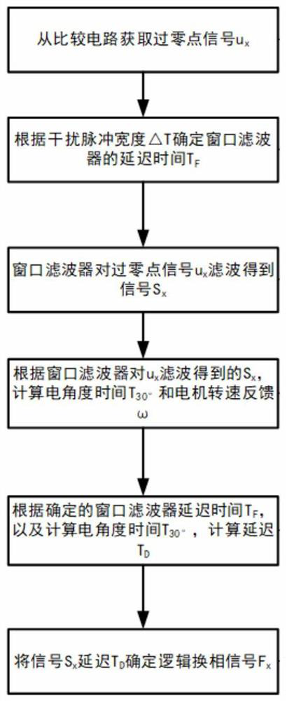
[0036] Such as figure 1 As shown, the present invention proposes a flow chart of a no-delay control method for a high-speed brushless DC motor, and the specific design includes:

[0037] Step S1: Obtain the zero-crossing signal u from the comparison circuit x ;

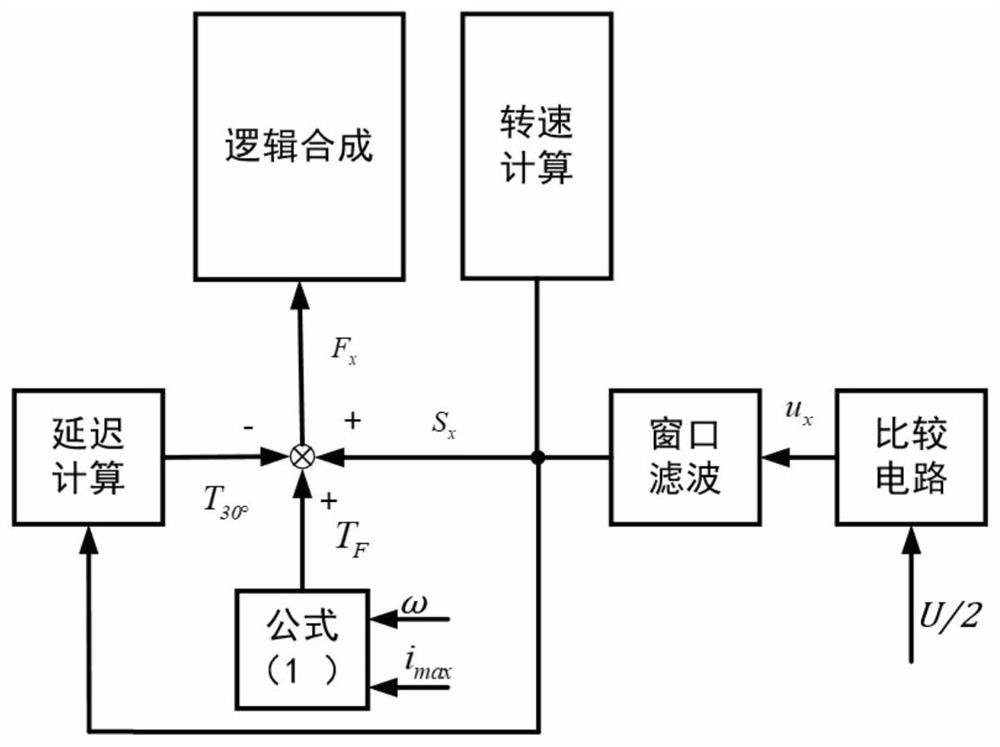
[0038] Step S2: The comparison circuit in the step S1 compares the voltage of a certain phase with U / 2 to obtain the zero-crossing point of the opposite electromotive force, where U is the bus voltage.

[0039] When one of the phases A, B, and C has a back EMF zero crossing point, as long as the terminal voltage of this phase is ...


PUM


Abstract

The invention relates to a delay-free control method for a high-speed brushless direct current motor. The method comprises the following steps: acquiring a zero crossing point signal ux from a comparison circuit; determining the delay time TF of the window filter according to the interference pulse width delta T; enabling the window filter to filter the zero crossing point signal ux to obtain a signal Sx; calculating electrical angle time T30 degrees and motor rotating speed feedback omega according to Sx obtained by filtering ux through a window filter; calculating delay TD according to the determined window filter delay time TF and the calculated electrical angle time T30 degrees; and finally, delaying the signal Sx by TD to determine a logic commutation signal Fx. The control device comprises a comparison circuit module, a window filtering module and a delay calculation module. According to the characteristics of interference signals, the window filter with controllable delay time is designed, interference in the phase current follow current process is removed through the window filter, clear counter electromotive force zero crossing point signals are obtained, and the method has the advantage of no filtering delay, and is scientific, easy to implement and suitable for brushless direct current motors with different parameters.

Description

technical field [0001] The invention relates to the technical field of motor control, in particular, the invention relates to a non-delay control method for detecting the zero-crossing point of the counter electromotive force of a high-speed brushless DC motor. Background technique [0002] Brushless DC motors based on electronic commutation instead of mechanical commutation have the advantages of high reliability and high efficiency, and have been widely used. In applications such as aviation and aerospace, due to the limitation of the application environment, the position sensor of the motor is usually omitted for safety reasons. The control methods of position sensorless brushless DC motor mainly include counter electromotive force zero-crossing detection method, terminal voltage comparison method and third harmonic method, etc. Among them, the back EMF zero-crossing detection method has become a more commonly used positionless control method because of its advantages of...

Claims


Application Information

Patent Timeline
Patent Type & Authority Applications(China)
IPC IPC(8): H02P6/08H02P6/15H02P6/182
CPCH02P6/08H02P6/15H02P6/182
Inventor 刘文建魏海峰王浩陈
Owner JIANGSU UNIV OF SCI & TECH
Why Eureka
Eureka Blog
Learn More