Oral cavity opening and closing system for stomatology department based on Internet of Things and use method of oral cavity opening and closing system
A technology of stomatology and Internet of Things, which is applied in the field of oral opening and closing system for stomatology, which can solve the problems of poor use effect, affect patients' emotions, and patients' discomfort in use, so as to improve the comfort of use, increase the trouble of operation, and avoid rotation Effect
- Summary
- Abstract
- Description
- Claims
- Application Information
AI Technical Summary
Problems solved by technology
Method used
Image
Examples
Embodiment 1
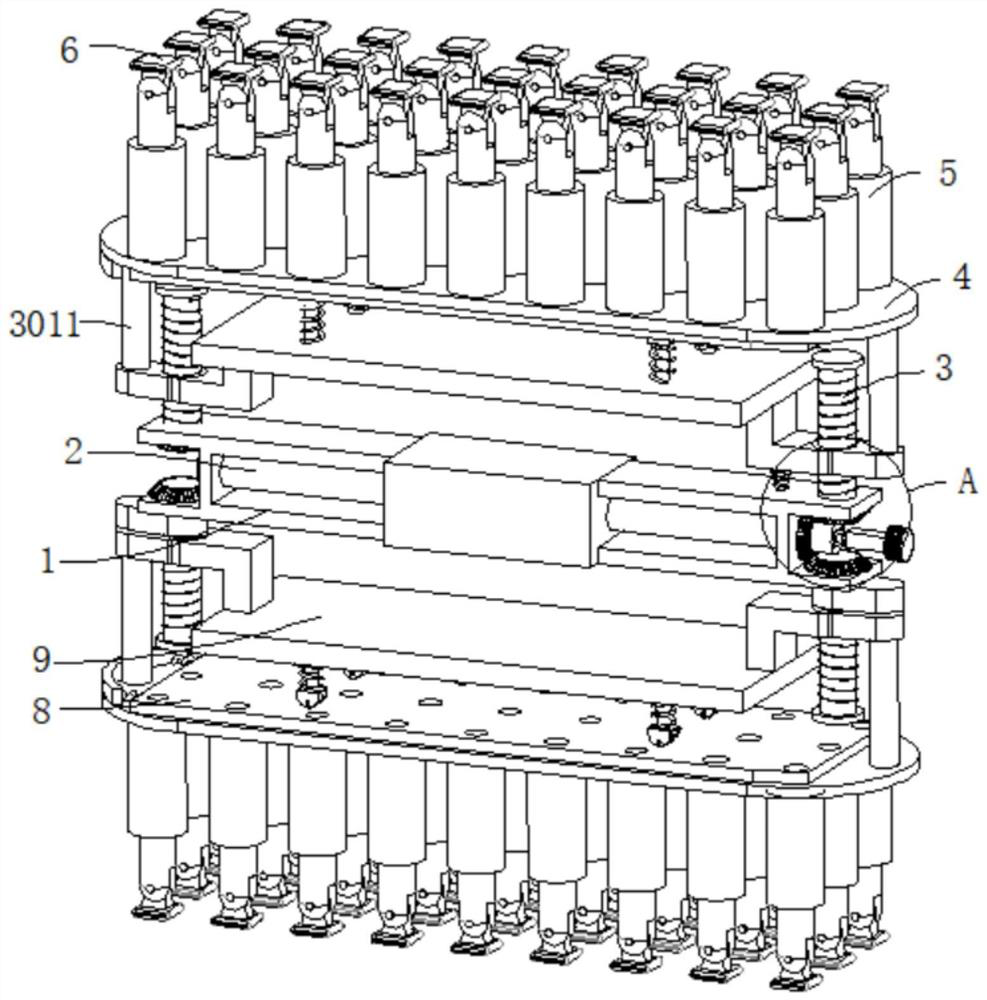
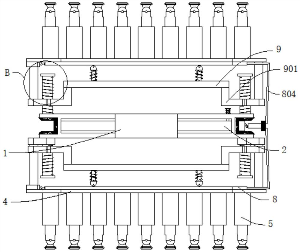
[0042] refer to figure 1 , figure 2 , image 3 , Figure 4 and Figure 5 , an oral opening and closing system for stomatology based on the Internet of Things, comprising a fixed frame 1, a rotating rod 2 is rotatably connected inside the fixed frame 1, threaded rods 3 are arranged at both ends of the fixed frame 1, and the rotating rod 2 and the threaded rod 3 is provided with a transmission assembly, the transmission assembly is arranged on the fixed frame 1, the outer wall of the threaded rod 3 is threadedly connected with a moving block 301, the outer wall of the moving block 301 is fixedly connected with a straight rod 3011, and the end of the straight rod 3011 away from the moving block 301 is connected with a The mounting plate 4 is provided with evenly distributed adjustable telescopic rods 5, the top of the adjustable telescopic rods 5 is provided with absorbent cotton 6 that fits with the inner wall of the oral cavity, and the outer wall of the mounting plate 4 is...
Embodiment 2
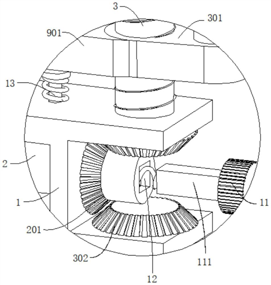
[0045] refer to image 3 , Figure 6 and Figure 7 , an oral opening and closing system for stomatology based on the Internet of Things, which is the same as that of Embodiment 1, furthermore, the transmission assembly includes a driving bevel gear 201 rotatably connected to the outer wall of the fixed frame 1 and a driven bevel gear 302 meshing with it , the driving bevel gear 201 is fixedly connected with the rotating rod 2, and the driven bevel gear 302 is fixedly connected with the threaded rod 3; 302 are engaged with each other, so that the threaded rod 3 rotates on the fixed frame 1, and then the mounting plate 4 is adjusted.
[0046] The adjustable telescopic rod 5 includes a sleeve 501 and a retractable rod 502. The bottom of the retractable rod 502 is connected with a sealing piston 503. The sealing piston 503 is slidably connected in the sleeve 501. A first The elastic element 504, the bottom wall of the sleeve 501 and the outer wall of the mounting plate 4 are pr...
Embodiment 3
[0049] refer to Figure 5 , Figure 6 and Figure 8 , an oral opening and closing system for stomatology based on the Internet of Things, which is the same as Embodiment 2, furthermore, the limiting mechanism includes a moving plate 8 that is slidably connected to the outer wall of the mounting plate 4, and the outer wall of the moving plate 8 is provided with a first The second through hole 801 matched with the through hole 505, the third elastic element 802 is connected to one end of the moving plate 8, the outer wall of the third elastic element 802 is connected with a support plate 803, the support plate 803 is fixedly connected with the mounting plate 4, and the moving plate 8 The end far away from the third elastic element 802 is connected with a pull cord 804 , and the end of the pull cord 804 far away from the moving plate 8 is connected with a knob assembly, and the knob assembly is connected with the rotating rod 2 .
[0050] Further, the limiting mechanism also in...
PUM
 Abstract
Description
Claims
Application Information
 - R&D
- Intellectual Property
- Life Sciences
- Materials
- Tech Scout
- Unparalleled Data Quality
- Higher Quality Content
- 60% Fewer Hallucinations
Browse by: Latest US Patents, China's latest patents, Technical Efficacy Thesaurus, Application Domain, Technology Topic, Popular Technical Reports.
© 2025 PatSnap. All rights reserved.Legal|Privacy policy|Modern Slavery Act Transparency Statement|Sitemap|About US| Contact US: help@patsnap.com


