Rotary tool head and floating device

A technology of floating devices and rotating tools, which is applied in the direction of manufacturing tools, additive processing, metal processing equipment, etc. It can solve the problems of low tool head life, reduce flash, avoid vibration and wear, and facilitate installation and debugging.

Active Publication Date: 2022-01-28
SOUTHWEST TECH & ENG INST
View PDF8 Cites 1 Cited by
  • Summary
  • Abstract
  • Description
  • Claims
  • Application Information

AI Technical Summary

Problems solved by technology

[0004] The object of the present invention is to provide a rotary tool head and its floating device to solve the problem of low life of the tool head

Method used


Image

  • Rotary tool head and floating device
  • Rotary tool head and floating device
  • Rotary tool head and floating device

Examples


Embodiment 1

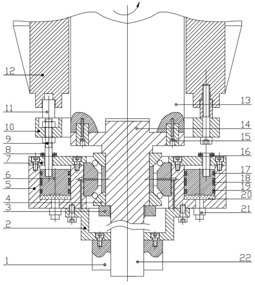
[0027] like Figure 1-8 As shown, a rotating tool head and its floating device include a mold base structure, a rotating structure and a tool head 22, the rotating structure drives the tool head 22 to rotate, and the rotating structure includes a rotating mechanism 13 and a transmission shaft 14, The lower end surface of the rotating mechanism 13 is screwed to the transmission key 15, and the transmission key 15 is used to drive the transmission shaft 14 to rotate. The upper end surface of the transmission shaft 14 is axially separated from the lower end surface of the rotation mechanism 13 and leaves a certain The gap is for the transmission shaft 14 to move in the axial direction. The transmission shaft 14 is connected to the tool head 22, and both are solid structures. The outer side of the transmission shaft 14 is sleeved with a floating structure, and the floating The structure is connected to the formwork structure, the transmission shaft 14 and the tool head 22 move in ...

Embodiment 2

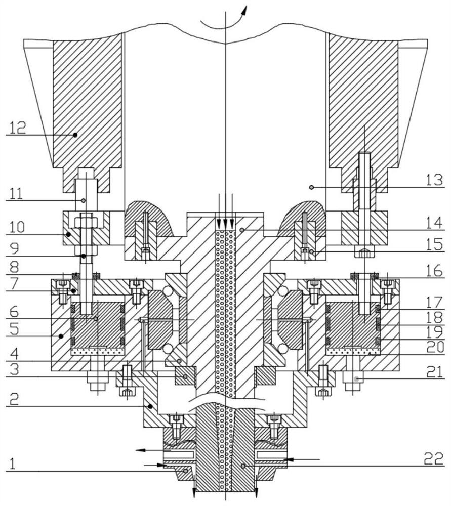
[0037] like figure 2 As shown, referring to the rotary tool head and its floating device in Embodiment 1, the rotary mechanism 13, the transmission shaft 14 and the tool head 22 are hollow structures connected with each other, and the outer side of the tool head 22 is pierced with an annular shell 1, A cooling water system and a gas protection system are arranged in the annular housing 1, the cooling water system includes a water inlet and a water outlet, the water flows around the tool head 22, the gas protection system includes an air inlet and an air outlet, The air outlet faces the working direction of the tool head 22 and is used for cooling the tool head 22 and preventing the influence of oxidation inclusions. The annular housing 1 , the fixed ring 2 and the annular cylinder 5 are connected into one body.

[0038] The tool head 22 is a hollow structure, suitable for friction additives, and its working process includes the following stages:

[0039] (1) Preparatory stag...


PUM


Abstract

The invention relates to the technical field of friction equipment, and discloses a rotary tool head and a floating device. The rotary tool head comprises a mold frame structure, a rotating structure and a tool head, wherein the rotating structure drives the tool head to rotate. The rotary tool head is characterized in that the rotating structure comprises a rotating mechanism and a transmission shaft, the rotating mechanism drives the transmission shaft to rotate through a transmission key, the transmission shaft is axially separated from the rotating mechanism, a gap is reserved between the transmission shaft and the rotating mechanism, the transmission shaft can move in the axial direction, the transmission shaft is connected with the tool head, a floating structure is arranged on the outer side of the transmission shaft in a sleeving mode, the transmission shaft is connected with the mold frame structure through the floating structure, the transmission shaft and the tool head slide in the axial direction along with the floating structure, and the advantages that the service life of the tool head is long and the blank forming quality is good are achieved.

Description

technical field [0001] The invention relates to the technical field of friction equipment, in particular to a rotary tool head and a floating device thereof. Background technique [0002] Document CN112496522 discloses a friction stir additive device and additive manufacturing method, including a tool head, a tool handle and a shaft sleeve. There is a connected hollow cavity in the handle for adding wire, so as to realize friction stir additive manufacturing. [0003] At present, the friction welding equipment in the prior art or the above-mentioned friction additive equipment all use rigid tool heads. Since the tool head is a rigid structure, it bears a lot of load and wears during the working process, and the working environment of the tool head is harsh. Severe wear, low service life, and affect the forming quality of additive products. Contents of the invention [0004] The object of the present invention is to provide a rotary tool head and its floating device to so...

Claims


Application Information

Patent Timeline
IPC IPC(8): B23K20/12B23K20/26B33Y10/00B33Y30/00
CPCB23K20/1245B23K20/26B33Y10/00B33Y30/00
Inventor 吴护林李忠盛黄树海戴明辉肖寒陈强
Owner SOUTHWEST TECH & ENG INST
Why Eureka
Try Eureka