A tank separation mechanism

A technology of telescopic mechanism and tank body, which is applied in the direction of conveyor objects, conveyor control devices, transportation and packaging, etc., which can solve the problems of long buffer channel, large floor area, extrusion deformation of tank body, etc., and achieve short buffer channel , small footprint and extended length

Active Publication Date: 2022-07-12
JOYEA CORP
View PDF0 Cites 0 Cited by
  • Summary
  • Abstract
  • Description
  • Claims
  • Application Information

AI Technical Summary

Problems solved by technology

[0004] 1. The structure of the cans on the conveyor is mostly a fixed structure, which causes the cans on each buffer channel to squeeze each other. If the tanks are not strong, it will also lead to extrusion deformation of the tanks, damage to the tanks, etc. the occurrence of the situation;
[0005] 2. If the cans are distributed unevenly on the tank lanes of the conveyor, the cans will block each other, and more seriously, the cans will accumulate and stay behind, and the entire assembly line will be paralyzed;
[0006] 3. The more cans are buffered on the conveyor, the longer the conveyor will be, which will result in a large footprint, a long buffer channel, and a waste of resources

Method used


Image

  • A tank separation mechanism
  • A tank separation mechanism
  • A tank separation mechanism

Examples


Embodiment Construction

[0031] The technical solutions in the embodiments of the present invention will be clearly and completely described below with reference to the accompanying drawings in the embodiments of the present invention. Obviously, the described embodiments are only a part of the embodiments of the present invention, rather than all the embodiments.

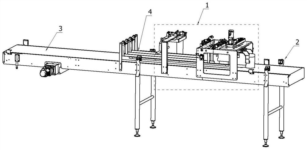
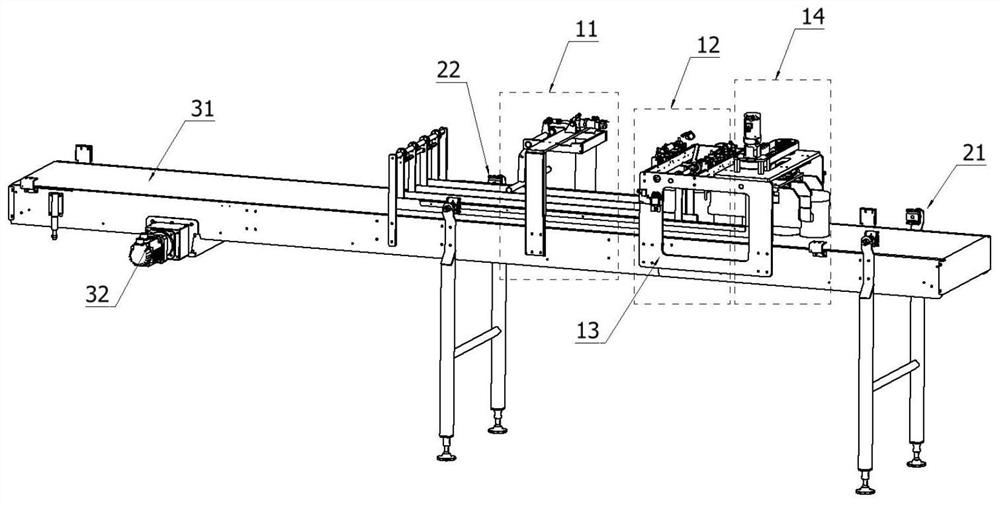
[0032]A tank lane separation mechanism includes a tank lane execution general module 1, a tank body detection device 2, a transmission device 3, and a track module 4. The tank lane execution overall module 1 includes a tank blocking follower component 11, and a total tank blocking mechanism. 12. The double-sided fixing plate 13, the tank body displacement general component 14, the tank blocking follower component 11 is fixed on the transmission device 3, the total tank blocking mechanism 12 is arranged above the transmission device 3, and the tank body is displaced The general component 14 is located above the transmission device 3 and is a...


PUM


Abstract

The invention discloses a tank lane separation mechanism, comprising a tank lane execution general module, a tank body detection device, a transmission device and a track module. The mutual cooperation between the side fixing plate and the overall displacement of the tank prevents the tanks from squeezing each other. No matter whether the tank is strong or not, it will not cause the tank to be squeezed and deformed, the tank will be damaged, and the tank will not be compressed. The front-side tank displacement part of the displacement general part and the rear-side tank displacement part act at the same time. When the operation is completed, there is a track channel to accommodate new cans to enter the tank to ensure continuous cans; Reasonable and even distribution, it will not cause the accumulation of jars in the rear, and the entire pipeline will be paralyzed; save space, for the case of a large number of jars, it will not cause the length of the transmission device to be extended, the footprint is small, the buffer channel is short, and resources will not be wasted .

Description

technical field [0001] The invention relates to the field of tank body lane separation in a production line, in particular to a tank lane separation mechanism. Background technique [0002] At present, there are multiple buffer channels in the can cache of the wrapping machine, and the finished cans are evenly distributed to each buffer channel through servo power. In order to store so many cans at the same time, the conveyor length of the can buffer channel should reach 4-5m or even longer, and the length of the whole equipment is very long, reaching more than 12 meters. [0003] There are certain shortcomings in the actual operation process: [0004] 1. The structure of the tank body on the conveyor is mostly a fixed structure, which causes the tanks on each buffer channel to squeeze each other. If the tank body is not strong, it will also lead to extrusion deformation of the tank body, damage to the tank body, etc. the occurrence of the situation; [0005] 2. If the ca...

Claims


Application Information

Patent Timeline
Patent Type & Authority Patents(China)
IPC IPC(8): B65G47/71B65G47/88B65G47/29B65G43/08
CPCB65G47/71B65G47/8807B65G47/295B65G43/08
Inventor 景建华殷祥根刘潇陈娟
Owner JOYEA CORP
Why Eureka
Try Eureka