Cast-in-place pile over-filling prevention device and using method of device
A cast-in-situ pile and anti-overrunning technology, which is applied in the direction of sheet pile wall, foundation structure test, construction, etc., can solve the problems of high cost, insufficient measurement accuracy, and improved operation requirements, and achieve accurate and timely results, simple device structure, and measurement high precision effect
- Summary
- Abstract
- Description
- Claims
- Application Information
AI Technical Summary
Problems solved by technology
Method used
Image

Examples
Embodiment Construction
[0026] The present invention will be further described below in conjunction with specific examples.
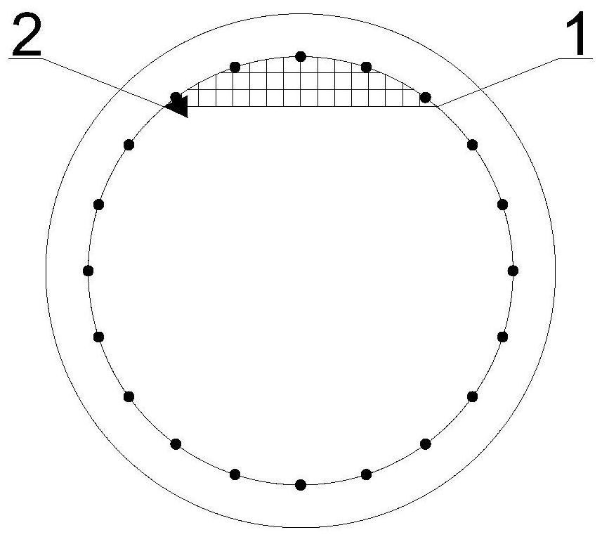
[0027] Such as figure 1 As shown, a device for preventing overfilling of cast-in-situ piles includes a metal mesh 1 and a triangular steel sheet 2 .
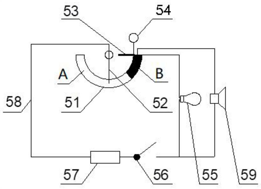
[0028] Such as figure 2 As shown, the superfill prompting instrument 5 includes a sliding rheostat 51, a slide bar 52, a one-way valve 53, a pulley 54, a reminder light 55, a closing switch 56, a storage battery 57, a closing circuit 58, and a warning bell 59.
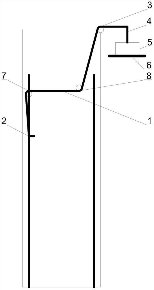
[0029] Such as image 3 As shown, a device for preventing overfilling of cast-in-situ piles includes a steel mesh 1, a triangular steel sheet 2, a pulley 3, a non-elastic stay rope 4, an overfilling prompter 5, a support 6, a pulley 7, and a pulley 8. The superfill prompting instrument 5 is placed on the support 6 and fixed with bolts. The super irrigation prompting instrument 5 is a portable super irrigation prompting instrument.
[0030] Determine the position of...
PUM
| Property | Measurement | Unit |
|---|---|---|
| Side length | aaaaa | aaaaa |
| Thickness | aaaaa | aaaaa |
| Diameter | aaaaa | aaaaa |
Abstract
Description
Claims
Application Information