
Grabbing structure for automatically grabbing pipe rod, lifting device of grabbing structure and equipment thereof

A technology of grabbing structure and lifting device, applied in drilling equipment, drill pipe, casing and other directions, can solve the problems of cumbersome installation process, high production cost, difficult operation, etc., and achieves low operation difficulty, low cost, and reduced operation. effect of difficulty

Active Publication Date: 2022-01-28
JIANGSU RUTONG PETRO MASCH CO LTD
View PDF6 Cites 0 Cited by
  • Summary
  • Abstract
  • Description
  • Claims
  • Application Information

AI Technical Summary

Problems solved by technology

[0005] The object of the present invention is to provide a grabbing structure for automatically grabbing pipe rods and its lifting device and equipment, so as to solve the problem of high production cost and complex structure of the manipulator for automatically grabbing pipe rods at the present stage proposed in the above background technology. The installation process is cumbersome and the operation is difficult

Method used


Image

  • Grabbing structure for automatically grabbing pipe rod, lifting device of grabbing structure and equipment thereof
  • Grabbing structure for automatically grabbing pipe rod, lifting device of grabbing structure and equipment thereof
  • Grabbing structure for automatically grabbing pipe rod, lifting device of grabbing structure and equipment thereof

Examples


Embodiment 1

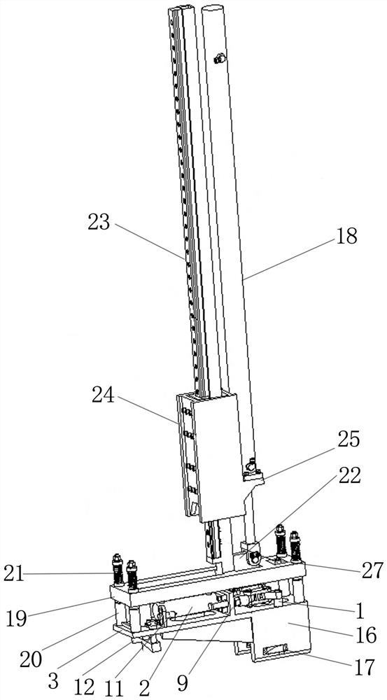
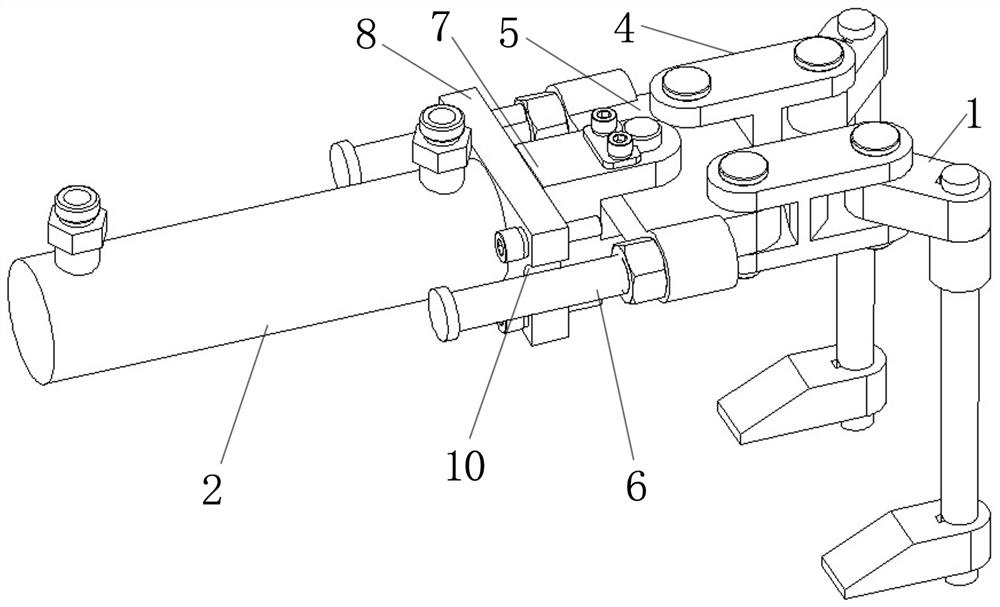
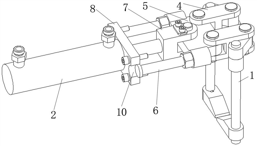
[0032] Such as Figure 1-Figure 3 As shown, a grabbing structure for automatically grabbing a pipe rod includes a claw 1, a grabbing liquid cylinder 2 and a claw base 3. The claw 1 is movably connected to the I-shaped connecting sleeve 4, and the connecting sleeve 4 It is fixedly connected to both ends of one side of the connecting plate 5 through bolt columns, and a guide rod 6 is respectively arranged at the other two ends of the connecting plate 5, and a clamping block 7 is fixedly arranged in the middle position of the other side of the connecting plate 5, and grabbing One end of the liquid cylinder 2 is fixedly provided with a guide plate 8, and both sides of the guide plate 8 are provided with grooves 10 matched with the guide rod 6 (such as Figure 2-3 As shown), there is a raised support 9 in the middle of the top of the claw base 3, the piston rod of the grasping cylinder 2 passes through the support 9 and is fixedly connected with the block 7, and the other end of th...

Embodiment 2

[0037] see Figure 1-6 , as another object of the present invention, provides the equipment of automatically grabbing pipe rod, is provided with above any lifting device on this equipment, therefore, this equipment can obtain any beneficial that above-described lifting device has. effect, which will not be repeated here.


PUM


Abstract

The invention discloses a grabbing structure for automatically grabbing a pipe rod, which comprises a grabbing mechanism, the grabbing mechanism is fixedly arranged on a claw base, one end of the claw base is provided with a sensing assembly which senses the grabbing mechanism, and one end of the grabbing mechanism is provided with a grabbing hydraulic cylinder which is matched with the sensing assembly. A support connected with the grabbing hydraulic cylinder is arranged in the middle of the claw base. The position of the pipe rod is fed back through the sensing assembly, the grabbing mechanism can accurately grab the pipe rod under feedback of the sensing assembly, then the grabbing hydraulic cylinder is used for driving the grabbing mechanism to clamp or loosen the pipe rod, the grabbing mechanism can clamp or loosen the pipe rod more flexibly, the operation difficulty is effectively reduced. The grabbing hydraulic cylinder and the grabbing mechanism are fixedly connected through the claw base, the structure is simplified, the installation process is simplified, meanwhile, cost is reduced, and the pipe rod conveying and placing efficiency is effectively improved.

Description

technical field [0001] The invention belongs to the technical field of oil field workover operation equipment, and in particular relates to a grabbing structure for automatically grabbing pipe rods, a lifting device and equipment thereof. Background technique [0002] Usually, several pipes and rods need to be used during workover operations in the oil field. The traditional transportation and placement of pipes and rods are carried out by manual rolling and pulling. risk of damage, etc. [0003] At present, the transportation and placement of pipes and rods is carried out by hoists or transporters, which can reduce the labor force. However, due to the harsh environment of oil field workover operations, there are greater safety risks in larger hoists or transporters, and the operation It is difficult, and it is not suitable for the placement of pipes and rods in oil field workover operations. [0004] At this stage, there is an automated manipulator for the transportation ...

Claims


Application Information

Patent Timeline
IPC IPC(8): E21B19/14
CPCE21B19/14Y02E30/30
Inventor 陈世龙王峰管永祥吕文杰
Owner JIANGSU RUTONG PETRO MASCH CO LTD
Learn More