Eureka AIR delivers breakthrough ideas for toughest innovation challenges, trusted by R&D personnel around the world.

Silicone oil clutch with front cover convenient and quick to disassemble

A silicone oil clutch, a convenient technology, applied in clutches, fluid clutches, engine cooling, etc., can solve problems such as increased engine resistance torque, increased power, and troublesome operation when removing the front cover.

Inactive Publication Date: 2022-01-28
江苏睿昕汽车科技有限公司
View PDF6 Cites 0 Cited by
  • Summary
  • Abstract
  • Description
  • Claims
  • Application Information

AI Technical Summary

Problems solved by technology

[0003] The object of the present invention is to address the deficiencies of the prior art, to provide a silicone oil clutch with a front cover that is convenient and quick to disassemble, so as to solve the following problems in the prior art proposed in the above-mentioned background technology, the front cover of the conventional silicone oil clutch The installation is connected and fixed by bolts and nuts. This structure is cumbersome to operate when the front cover needs to be disassembled. The existing silicone oil clutch mainly adopts a single-stage fan structure, and then the engine drives the silicone oil clutch, and the silicone oil clutch drives the fan to rotate. The movement forms a single-stage fan structure. Under certain air volume conditions, the diameter of the fan will be larger, which will bring problems such as increased resistance torque, increased power consumption, and increased noise to the engine.

Method used


Image

  • Silicone oil clutch with front cover convenient and quick to disassemble
  • Silicone oil clutch with front cover convenient and quick to disassemble
  • Silicone oil clutch with front cover convenient and quick to disassemble

Examples


Embodiment Construction

[0037] The following will clearly and completely describe the technical solutions in the embodiments of the present invention with reference to the accompanying drawings in the embodiments of the present invention. Obviously, the described embodiments are only some, not all, embodiments of the present invention. Based on the embodiments of the present invention, all other embodiments obtained by persons of ordinary skill in the art without making creative efforts belong to the protection scope of the present invention.

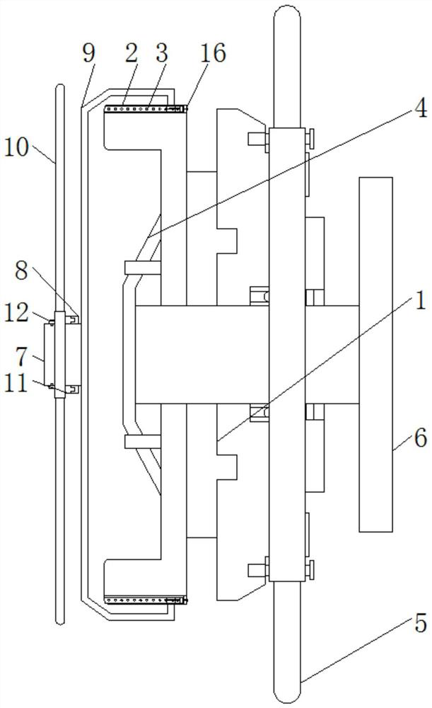
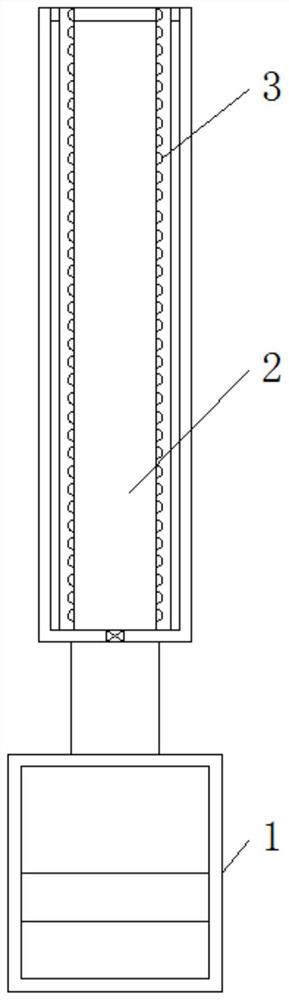
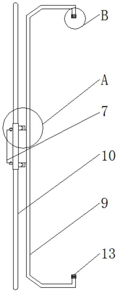
[0038] see Figure 1-6 , the present invention provides a technical solution: a silicone oil clutch with a front cover that can be easily and quickly disassembled, such as figure 1 , figure 2 and image 3 As shown, a connection groove is provided on one side of the housing 1, and a mounting groove 2 is provided on the other side of the housing 1. A card slot 3 is provided inside the installation groove 2, and a threaded connection groove is opened through o...


PUM


Abstract

The invention discloses a silicone oil clutch with a front cover convenient and quick to disassemble. The silicone oil clutch comprises a shell, an oil blocking piece, a first fan blade, a flange connecting shaft, a connecting shaft, a second fan blade, a sliding block and an auxiliary limiting device, wherein a connecting groove is formed in one side of the shell, and a mounting groove is formed in the other side of the shell; a clamping groove is formed in the mounting groove; a threaded connecting groove is formed in one side of the interior of the mounting groove in a penetrating mode; the oil blocking piece is mounted on the other side of the shell; the first fan blade penetrates through one side of the shell and penetrates through the connecting groove through a connecting bolt to be fixedly connected with one side of the shell; one end of the flange connecting shaft penetrates through the shell to be connected; a mounting groove is formed in one end of the connecting shaft, and theother end of the connecting shaft is fixed with a concave block; and meanwhile, the other end of the connecting shaft is fixedly connected with the front end cover. According to the silicone oil clutch with the front cover convenient and quick to disassemble, the protruding block and the through hole connecting block are arranged, and the whole second fan blade can be conveniently and rapidly installed and connected in a matched mode in the matched connection process through the protruding block and the concave block.

Description

technical field [0001] The invention relates to the technical field of silicone oil clutches, in particular to a silicone oil clutch with a front cover that can be easily and quickly disassembled. Background technique [0002] During the driving process of the car, due to the change of environmental conditions and operating conditions, the thermal condition of the engine is also changing, so the cooling intensity of the engine must be adjusted at any time. For example, in the hot summer, the engine works at low speed and under heavy load. When the temperature is very high, the fan should rotate at high speed to increase the cooling air volume and enhance the heat dissipation capacity of the radiator. In cold winter, when the coolant temperature is low or when the car is driving at high speed and there is strong headwind blowing through the radiator, It becomes meaningless for the fan to continue to work. Therefore, it is very important to adjust the cooling intensity of the ...

Claims


Application Information

Patent Timeline
IPC IPC(8): F01P7/04F16D35/00
CPCF01P7/042F16D35/00
Inventor 陆霜岳胜桥李冬鹰
Owner 江苏睿昕汽车科技有限公司
Why Eureka
Eureka Blog
Learn More