U-shaped infolding rotating mechanism with combination of inner chute and semicircle

A rotating mechanism and semi-circular arc technology, which is applied in the direction of mechanical equipment, shafts, bearings, pivots, etc., can solve the problems of inconvenient industrial manufacturing and large number of spare parts, and achieve the effect of simple and effective overall structure design and easy industrial implementation

Pending Publication Date: 2022-01-28
DONGGUAN JINFENG ELECTRONICS
0 Cites 0 Cited by

AI-Extracted Technical Summary

Problems solved by technology

[0003] To achieve the above technical effects, the biggest technical problem is directly transferred from the design of the screen to the design technology of the rotating shaft. How to realize the inward folding requires a special rotating mechanism, not only considering the possibilit...

Method used

Realize 0 degree-180 degree motion locus tangent point constant U-shaped inner bending rotation by oblique slide block relatively sliding in described inner chute, realize rotation by the cooperation of curved groove and rotating column, curved groove and rotating column The distribution position can be flexibly adjusted, and can be arbitrarily set on the turret or the connecting and positioning movable block. The arc-shaped slider and the arc-shaped c...

Abstract

The invention discloses a U-shaped infolding rotating mechanism with combination of an inner chute and a semicircle, which comprises a rotating shaft, the rotating shaft comprises a rotating mechanism, and the rotating mechanism comprises two groups of rotating frames which are transversely distributed, and a chute movable block and a connection positioning movable block which are longitudinally distributed; two groups of interaction blocks which are transversely distributed are arranged between the chute movable block and the connection positioning movable block, inclined sliding blocks and arc-shaped grooves are respectively arranged on two sides of the interaction blocks, two groups of inner inclined grooves which are respectively inclined inwards are formed in the chute movable block, arc-shaped sliding blocks are arranged on the rotating frame, the arc-shaped sliding blocks slide in the arc-shaped grooves. The inclined sliding block relatively slides in the inner inclined groove to drive the rotating mechanism to ascend, and meanwhile U-shaped inwards-bent rotation with the motion track tangent point unchanged at the angle ranging from 0 degree to 180 degrees is achieved. The rotating frame and the connection positioning movable block are in sliding fit through a sliding column and a curve groove to achieve rotation.

Application Domain

Technology Topic

Image

  • U-shaped infolding rotating mechanism with combination of inner chute and semicircle
  • U-shaped infolding rotating mechanism with combination of inner chute and semicircle
  • U-shaped infolding rotating mechanism with combination of inner chute and semicircle

Examples

  • Experimental program(2)

Example Embodiment

[0046] Example 1:
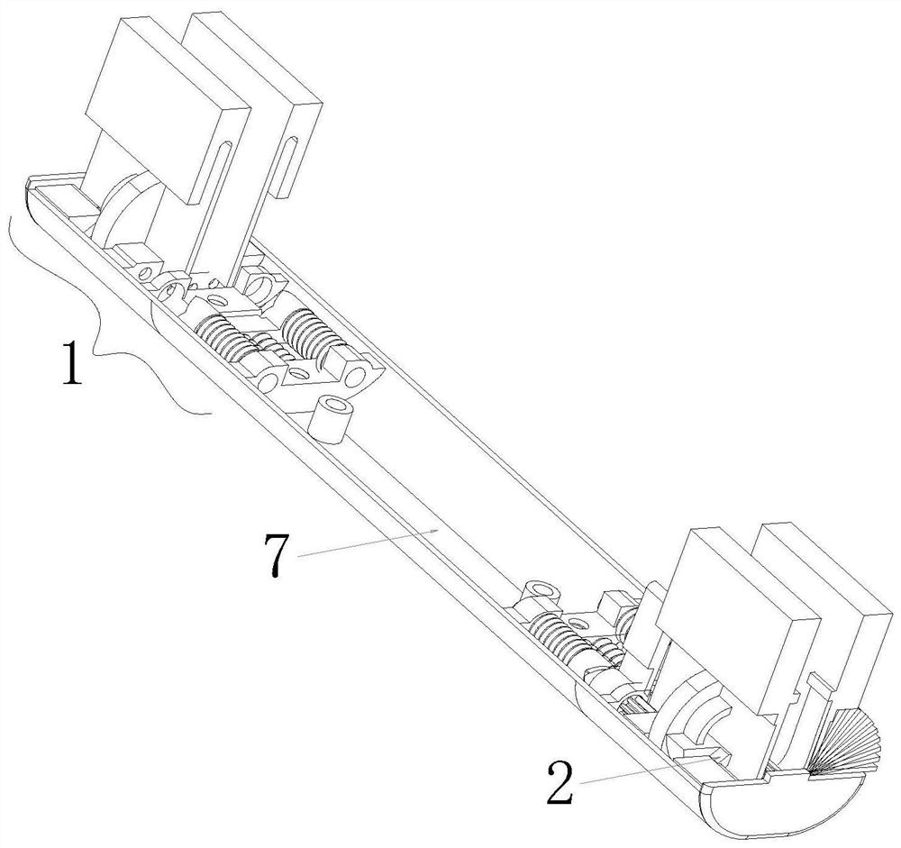
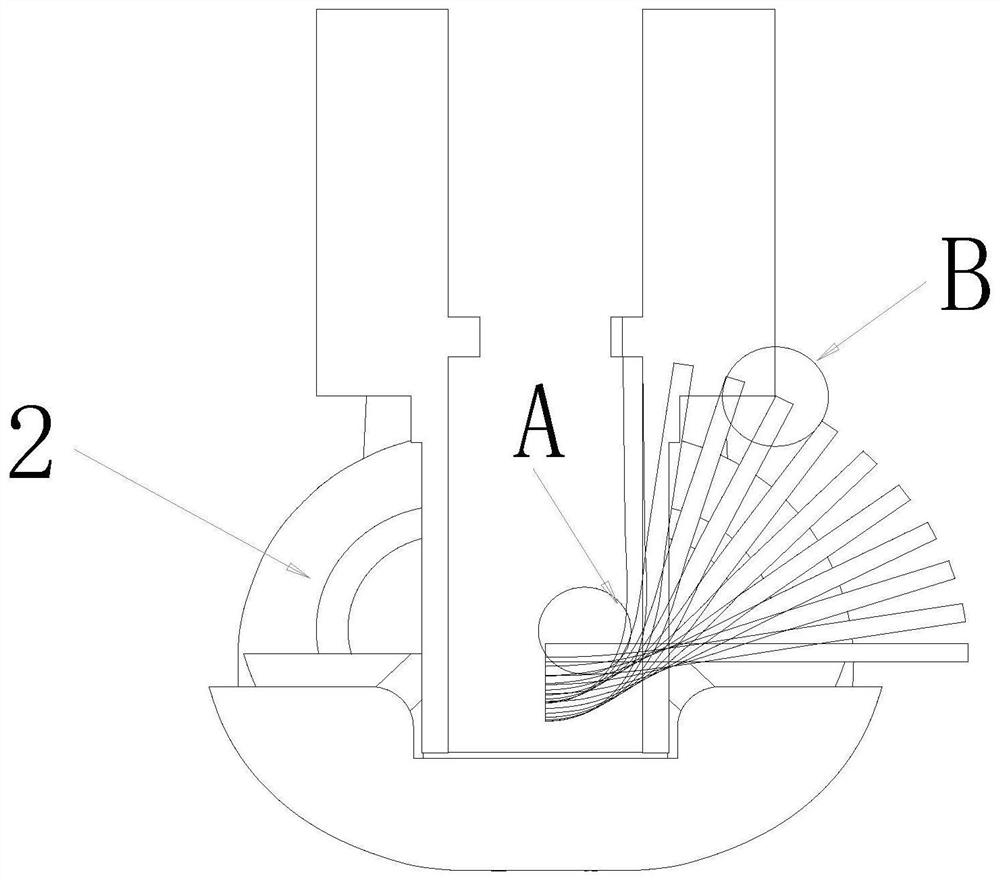
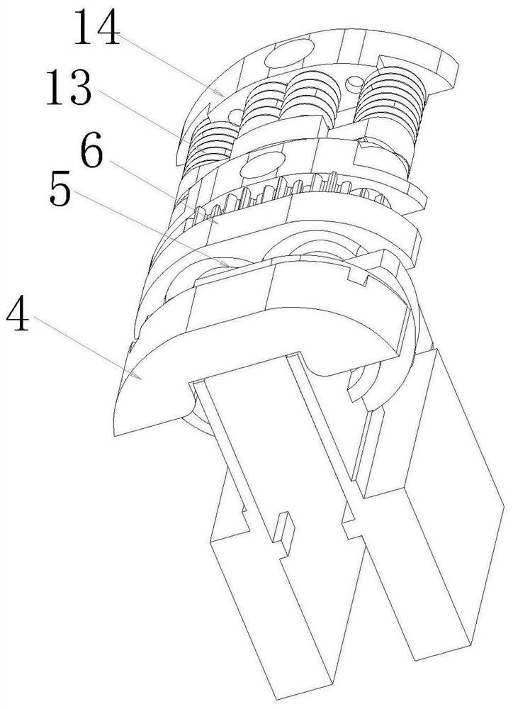
[0047] like Figure 8-16 As shown, the U-shaped inward turning mechanism disclosed in this embodiment, which combines an inner chute and a semicircular arc, includes a rotating shaft 1, and the rotating shaft 1 includes a rotating mechanism 2, and the rotating mechanism 2 includes two groups of horizontally distributed rotating mechanisms. Frame 3 and vertically distributed chute movable block 4, connecting and positioning movable block 5, two groups of interactive blocks 6 distributed horizontally are provided between the described chute movable block 4 and the described connecting and positioned movable block 5, and the interactive block 6 Both sides are respectively provided with oblique sliders 61 and arc-shaped grooves 62, two groups of inner inclined grooves 41 are arranged on the movable block 4 of the chute respectively, and the turret 3 is provided with arc-shaped sliders 31. The arc-shaped slider 31 slides in the arc-shaped groove 62, and the oblique slider 61 slides relatively in the inner chute 41, driving the rotating mechanism 2 to rise to achieve 0°- 180-degree motion track tangent point unchanged U-shaped inward bending rotation;
[0048] The rotation between the turret 3 and the connecting and positioning movable block 5 is achieved through sliding cooperation between the sliding column 101 and the curved groove 102 . The curved groove 102 is set on the turret 3 , and the sliding column 101 is set on the connecting and positioning movable block 5 . One of the interactive blocks 6 is provided with an interactive sliding block 63 , and the other interactive block 6 is provided with an interactive chute 64 , and the interactive sliding block 63 slides in the interactive chute 64 to realize the interactive movement of the interactive block.

Example Embodiment

[0049] Example 2:
[0050] like Figure 9-25As shown, the U-shaped inward turning mechanism disclosed in this embodiment, which combines an inner chute and a semicircular arc, includes a rotating shaft 1, and the rotating shaft 1 includes a rotating mechanism 2, and the rotating mechanism 2 includes two groups of horizontally distributed rotating mechanisms. Frame 3 and vertically distributed chute movable block 4, connecting and positioning movable block 5, two groups of interactive blocks 6 distributed horizontally are provided between the described chute movable block 4 and the described connecting and positioned movable block 5, and the interactive block 6 Both sides are respectively provided with oblique sliders 61 and arc-shaped grooves 62, two groups of inner inclined grooves 41 are arranged on the movable block 4 of the chute respectively, and the turret 3 is provided with arc-shaped sliders 31. The arc-shaped slider 31 slides in the arc-shaped groove 62, and the oblique slider 61 slides relatively in the inner chute 41, driving the rotating mechanism 2 to rise to achieve 0°- 180-degree motion track tangent point unchanged U-shaped inward bending rotation;
[0051] The rotation between the turret 3 and the connecting and positioning movable block 5 is achieved through sliding cooperation between the sliding column 101 and the curved groove 102 . The curved groove 102 is set on the connecting and positioning movable block 5 , and the sliding column 101 is set on the turret 3 . One of the interactive blocks 6 is provided with an interactive sliding block 63 , and the other interactive block 6 is provided with an interactive chute 64 , and the interactive sliding block 63 slides in the interactive chute 64 to realize the interactive movement of the interactive block.
[0052] In this patent, in addition to the above two groups of implementation methods, a set of connecting parts can be set between the chute movable block and the connecting and positioning movable block, and the sliding column is arranged on the connecting part to slide and connect with the curved groove of the turret. The connecting parts mentioned here can be two sets of balance wheels or other structural parts that can realize swing connection.

PUM

no PUM

Description & Claims & Application Information

We can also present the details of the Description, Claims and Application information to help users get a comprehensive understanding of the technical details of the patent, such as background art, summary of invention, brief description of drawings, description of embodiments, and other original content. On the other hand, users can also determine the specific scope of protection of the technology through the list of claims; as well as understand the changes in the life cycle of the technology with the presentation of the patent timeline. Login to view more.

Similar technology patents

Ship waste gas pollutant treatment apparatus

PendingCN110898653AEasy contact reactionThe overall structure design is simpleGas treatmentDispersed particle separationExhaust fumesPollutant
Owner:YANTAI ZHONGNUO ELECTROMECHANICAL INTEGRATED TECH CO LTD

Yarn spinning mechanism

PendingCN110699796AThe overall structure design is simpleReduce work flowPiercing arrangementsYarnStructural engineering
Owner:ANHUI RIFA TEXTILE MACHINERY

Folding mechanism and scooter

PendingCN114179952AThe overall structure design is simpleEasy to foldFoldable cyclesStructural engineeringMechanical engineering
Owner:ZHEJIANG OKAI VEHICLE CO LTD +2

Lever-type loop

InactiveCN104307894AThe overall structure design is simpleEasy to replace partsFlexible work arrangmentsMetal rolling arrangementsEngineeringMechanical engineering
Owner:JIANGSU YONGGANG GROUP CO LTD

Classification and recommendation of technical efficacy words

  • Ease of industrial implementation
  • The overall structure design is simple

Device and method for balancing alumina concentration of aluminium electrolysis tank

InactiveCN103014773AEase of industrial implementationAvoid low alumina concentrationsAluminiumControl system
Owner:GUIZHOU BRANCH CHINA ALUMINUM IND

Method for preparing compound in category of cyanopyridine

Owner:上海安基生物科技股份有限公司

Method for eliminating sulphur in high sulfur petroleum coke combustion flue gas

ActiveCN101185834AReliable technologyEase of industrial implementationDispersed particle separationChemistryRefinery
Owner:GUIZHOU BRANCH CHINA ALUMINUM IND

Functional polyamide and continuous production method thereof

ActiveCN109762162AEase of industrial implementationRealize large-scale industrialized continuous productionPrepolymerPolyamide
Owner:CHINESE TEXTILE ACAD +1

Automatic racking device for drill rod

Owner:建湖县鸿达阀门管件有限公司

Liquid-state heavy metal oxygen concentration control solid-liquid exchange reaction apparatus under flowing working condition

ActiveCN104392755AThe overall structure design is simpleEasy to operate and implementNuclear energy generationNuclear monitoringChemistryHeavy metals
Owner:HEFEI INSTITUTES OF PHYSICAL SCIENCE - CHINESE ACAD OF SCI

Medical tape cutter

InactiveCN106344283AThe overall structure design is simpleWide range of useBandagesEngineeringMechanical engineering
Owner:宁芳
Why Eureka
Try Eureka