Yarn spinning mechanism

A yarn and yarn storage technology, which is applied to spinning machines, textiles, papermaking, jointing devices, etc., can solve the problems of low efficiency and long operation time of splicing trolleys, and achieve simple overall structure design and reduce splicing Operation time and quality improvement effect

Pending Publication Date: 2020-01-17
ANHUI RIFA TEXTILE MACHINERY
View PDF1 Cites 0 Cited by
  • Summary
  • Abstract
  • Description
  • Claims
  • Application Information

AI Technical Summary

Problems solved by technology

The above solution still does not completely solve all the problems, there is still friction between the brake part and the package, the contact between the reverse roller and the package, and sometimes the guide part (big suction nozzle) cannot catch the

Method used


Image

  • Yarn spinning mechanism
  • Yarn spinning mechanism
  • Yarn spinning mechanism

Examples


Embodiment Construction

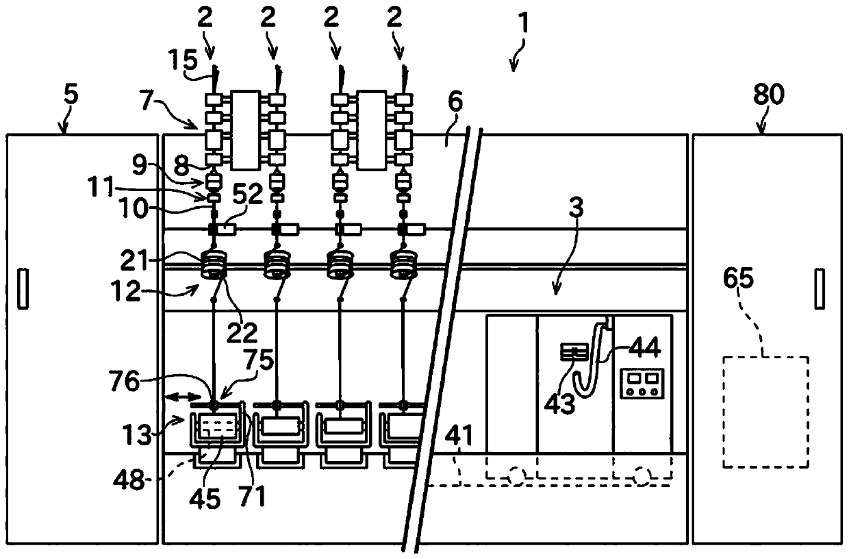
[0034] refer to Figure 1 to Figure 11 The specific implementation of a yarn spinning mechanism of the present invention will be further described. In addition, "upstream" and "downstream" in this specification are actually upstream and downstream of the running direction of the yarn during spinning.

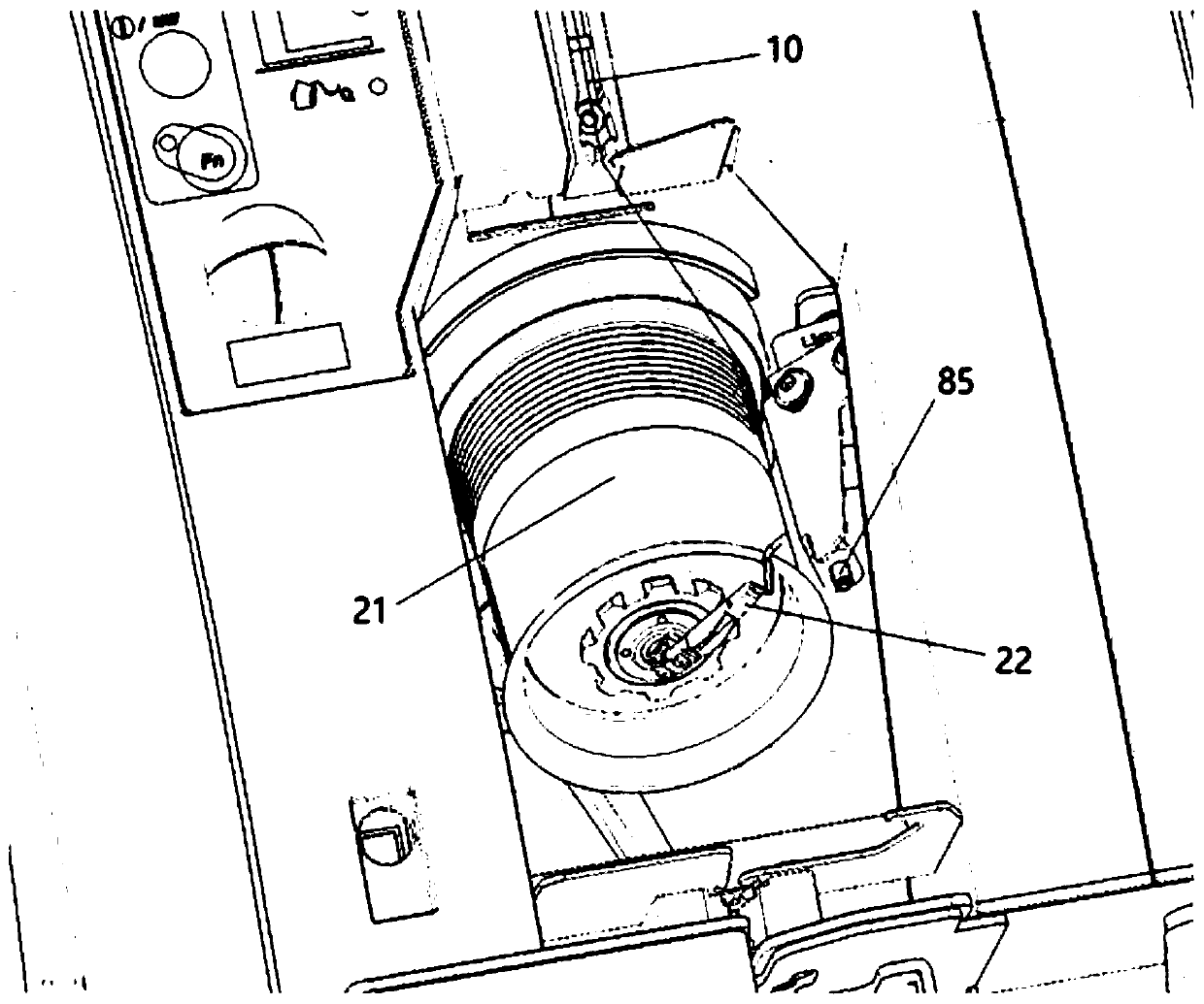
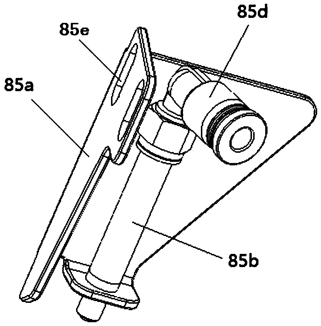
[0035] Such as figure 1 As shown, the fiber spinning machine 1 is provided with a plurality of spinning mechanisms 2 arranged in a row, and the spinning machine 1 has a splicing operation trolley 3, a negative pressure fan 80, and a control unit 5 installed on the headstock. Each spinning mechanism 2 is provided with a drafting device 7, a spinning part 9, an output device 11, a yarn storage device 12, and a winding part 13 as a main mechanism in sequence from upstream to downstream, and the yarn storage device 12 includes a yarn storage roller 21 And the yarn guide flyer 22, one side of the yarn guide flyer 22 is provided with a retractable and movable flyer stopper 85, and th...


PUM


Abstract

The invention discloses a yarn spinning mechanism which comprises a drafting device, a spinning portion, an output device, a yarn storing device and a winding portion sequentially from top to bottom.The yarn storing device comprises a yarn storing roller and a yarn guiding ingot wing, an extensible and movable ingot wing retainer is arranged on one side of the yarn guiding ingot wing and controlsthe yarn storing device to complete yarn unwinding during yarn breaking, and the winding portion is connected with a braking portion driving the same to rotate independently. The yarn spinning mechanism is simple in integral structure design, an intermittent braking mode of winding, rotating and stopping the yarn spinning mechanism is abandoned, and time for reversely winding a reverse rotation roller, capturing a yarn spinning head guide portion and retreating yarn fault is omitted, so that operation process and twist-connecting operation time are reduced, working efficiency is improved, relative friction of the yarn is reduced, and quality of spun yarn is improved.

Description

technical field [0001] The invention relates to the technical field of spinning machinery and equipment, and more specifically relates to a yarn spinning mechanism. Background technique [0002] Spinning machines that apply twists to fibers to generate spun yarns and wind them into packages are well known. The spinning machines described in the literature produce compressed air in the spinning chamber by jetting compressed air from the air spinning nozzle. The swirling airflow imparts twist to the fiber bundle to produce a yarn. Conventionally, a spinning unit is known that produces a spun yarn by drafting a fiber bundle and twisting the drafted fiber bundle. The winding part that makes the package by winding the spun yarn. [0003] In the past, the spinning machine with a plurality of spinning units is known to us. When the continuous state of spinning in one spinning unit is cut off, the spinning machine is equipped with a device that travels to the spinning unit for spl...

Claims


Application Information

Patent Timeline
IPC IPC(8): D01H15/00
CPCD01H15/00
Inventor 陈国樑张斌严登科戴小平邵开元潘凯凯张越锋
Owner ANHUI RIFA TEXTILE MACHINERY
Why Eureka
Try Eureka