Ship waste gas pollutant treatment apparatus

A pollutant treatment and waste gas technology, applied in gas treatment, dispersed particle separation, membrane technology, etc., can solve problems such as poor treatment effect and insufficient contact between waste gas and spray liquid, and achieve a simple overall structure design and convenient contact. Good response and treatment effect

Pending Publication Date: 2020-03-24
YANTAI ZHONGNUO ELECTROMECHANICAL INTEGRATED TECH CO LTD
View PDF0 Cites 0 Cited by
  • Summary
  • Abstract
  • Description
  • Claims
  • Application Information

AI Technical Summary

Problems solved by technology

[0002] Existing ships use heavy oil as fuel, and heavy oil will produce a large amount of exhaust gas during the combustion process. The existing purification treatment device generally adopts the method of connecting the waste to the washing tower and contacting the spray liquid, and the waste gas in the

Method used


Image

  • Ship waste gas pollutant treatment apparatus
  • Ship waste gas pollutant treatment apparatus
  • Ship waste gas pollutant treatment apparatus

Examples


Example Embodiment

[0020] The following will clearly and completely describe the technical solutions in the embodiments of the present invention with reference to the accompanying drawings in the embodiments of the present invention. Obviously, the described embodiments are only part of the embodiments of the present invention, not all of them. Based on the embodiments of the present invention, all other embodiments obtained by persons of ordinary skill in the art without creative efforts fall within the protection scope of the present invention.

[0021] It should be noted that all directional indications (such as up, down, left, right, front, back...) in the embodiments of the present invention are only used to explain the relationship between the components in a certain posture (as shown in the accompanying drawings). Relative positional relationship, movement conditions, etc., if the specific posture changes, the directional indication will also change accordingly.

[0022] In addition, the ...


PUM


Abstract

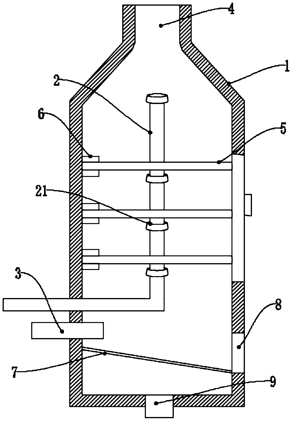
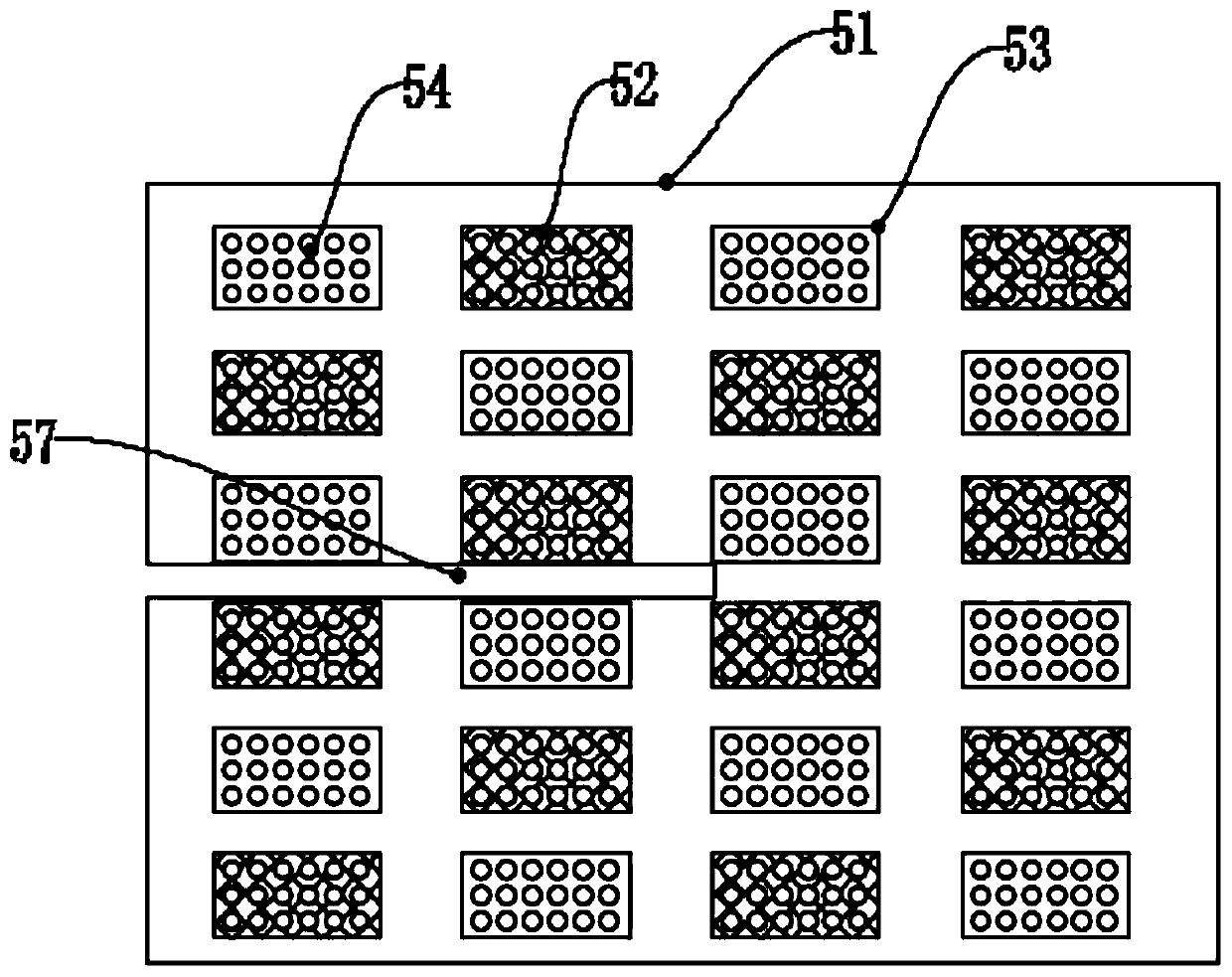
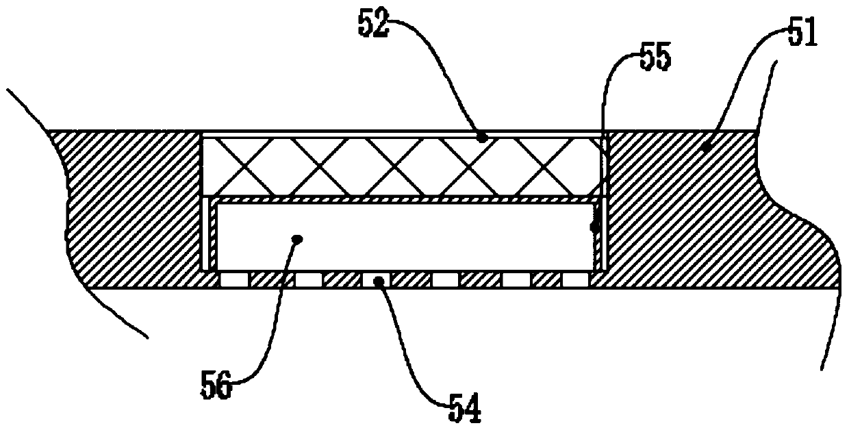
The invention discloses a ship waste gas pollutant treatment apparatus. The apparatus comprises a washing tower and a spraying pipe arranged in the washing tower, a waste gas inlet is arranged at thebottom of the washing tower, a waste gas outlet is arranged at the top of the washing tower, and multiple layers of filtering devices are arranged in the washing tower; every filtering device comprises a mounting plate and water-absorbing filter cotton placed on the mounting plate; the mounting plate is provided with a plurality of storage grooves for storing the water-absorbing filter cotton, andthe bottom of each storage groove is provided with a plurality of small holes; and the water-absorbing filter cottons are placed in the storage grooves at one interval of every mounting plate, and the water-absorbing filter cotton storage positions of the adjacent filtering devices are mutually staggered. The multiple layers of filtering devices make waste gas undergo multilayer filtration and fully contact and react with a spraying liquid, and the water-absorbing filter cottons of all the filtering devices are designed in the staggered mode to facilitate the contact reaction; and the apparatus has the advantages of simple and reasonable overall structural design, full contact reaction and good treatment effect.

Description

technical field [0001] The invention relates to the technical field of ship drainage, and relates to ship waste gas pollutant treatment equipment. Background technique [0002] Existing ships use heavy oil as fuel, and heavy oil will produce a large amount of exhaust gas during the combustion process. The existing purification treatment device generally adopts the method of connecting the waste to the washing tower and contacting the spray liquid, and the waste gas in the washing tower The spray liquid is generally sprayed down through the spray head located near the exhaust port, and the waste is discharged from the bottom of the washing tower upwards, so as to contact and react with the spray liquid. The contact of the drench is not sufficient, and the treatment effect is not good. Contents of the invention [0003] In order to solve the above problems, the present invention proposes a ship exhaust gas pollutant treatment equipment with simple structure, good treatment ...

Claims


Application Information

Patent Timeline
IPC IPC(8): B01D53/78B01D53/92B01D53/38
CPCB01D53/38B01D53/78B01D53/92B01D2258/01B01D2258/0283
Inventor 马越郝进伟曹贻社杨宏旺
Owner YANTAI ZHONGNUO ELECTROMECHANICAL INTEGRATED TECH CO LTD
Why Eureka
Try Eureka