Mobile antenna test rotary table with self-locking function
A mobile and functional technology, applied in antenna radiation patterns, measuring devices, measuring electrical variables, etc., can solve the problems of inconvenient movement and easy transfer, and achieve the effect of expanding the scope of use and improving portability
- Summary
- Abstract
- Description
- Claims
- Application Information
AI Technical Summary
Problems solved by technology
Method used
Image
Examples
Embodiment 1
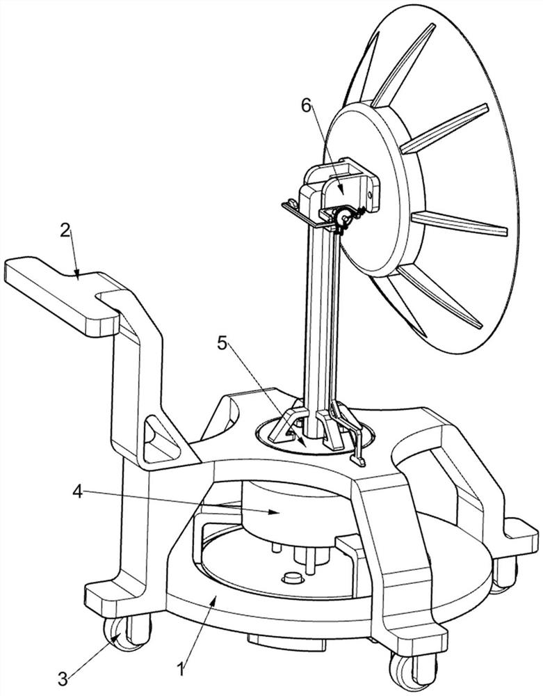
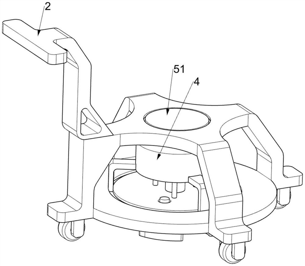
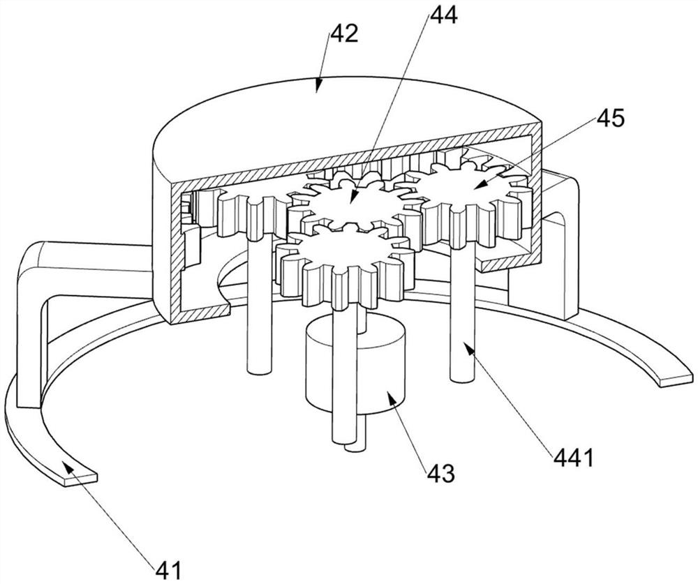
[0043] A mobile antenna test turntable with self-locking function, such as Figure 1-9As shown, it includes a support frame 1, a handle 2, a rotating wheel 3, a speed reduction mechanism 4, a rotation mechanism 5, a first support mechanism 6, an autorotation mechanism 7 and a first locking mechanism 8, and the support frame 1 is fixedly connected with a handle 2. , the support frame 1 is distributed and rotated in the upper circumference and is connected with four rotating wheels 3 for assisting people to push the equipment to move. The support frame 1 is provided with a deceleration mechanism 4, and the deceleration mechanism 4 is provided with a rotation mechanism for the horizontal rotation of the equipment. 5. The rotation mechanism 5 is provided with a first support mechanism 6, and the first support mechanism 6 is provided with an autorotation mechanism 7 for pitching and rotating the equipment, and the first support mechanism 6 is provided with a first stop for preventin...
Embodiment 2
[0053] On the basis of Example 1, such as Figure 10-12 As shown, a pushing mechanism 9 is also included, and the pushing mechanism 9 is located on the second fixed mount 81. The pushing mechanism 9 includes a wedge-shaped frame 91, a third fixed mount 92, a second sliding frame 93, a fourth wedge-shaped block 94 and a first wedge-shaped block 94. Four return springs 95, the turret 62 is fixedly connected with a wedge-shaped frame 91, the second fixed frame 81 is fixedly connected with a third fixed frame 92, the third fixed frame 92 is slidably connected with a second sliding frame 93, and the second sliding The frame 93 top has a rectangular hole, the second sliding frame 93 is fixedly connected with a fourth wedge block 94, the fourth wedge block 94 is a slope structure near the second fixed frame 81 side, the fourth wedge block 94 and the third fixed frame A fourth return spring 95 for driving the fourth wedge block 94 to reset is connected between the 92 .
[0054] Also ...
Embodiment 3
[0060] On the basis of Example 2, such as Figure 13 As shown, a second support mechanism 12 is also included, and the second support mechanism 12 for improving the stability of the equipment is arranged on the bidirectional motor 43. The second support mechanism 12 includes a threaded block 121, a threaded plate 122, a fixed ring 123, slide bar 124 and the seventh back-moving spring 125, one end of the output shaft of the bidirectional motor 43 below is fixedly connected with a threaded block 121, the threaded block 121 is externally threaded, and the threaded block 121 is rotatably connected with a fixed ring 123, and the fixed ring 123 The upper part is fixedly connected with a threaded plate 122, the interior of the threaded plate 122 is threaded, and the top of the threaded plate 122 is fixedly connected with a pair of sliding rods 124, the sliding rods 124 are cylindrical, the sliding rods 124 pass through the support frame 1, the support frame 1 and the threaded plate 12...
PUM
 Abstract
Description
Claims
Application Information
 - R&D
- Intellectual Property
- Life Sciences
- Materials
- Tech Scout
- Unparalleled Data Quality
- Higher Quality Content
- 60% Fewer Hallucinations
Browse by: Latest US Patents, China's latest patents, Technical Efficacy Thesaurus, Application Domain, Technology Topic, Popular Technical Reports.
© 2025 PatSnap. All rights reserved.Legal|Privacy policy|Modern Slavery Act Transparency Statement|Sitemap|About US| Contact US: help@patsnap.com


