Structure and installation method of flow-through type profile tower plate

A profile and tray technology, which is applied in the structure and installation field of through-flow profile trays to prevent follow-up, improve efficiency, and solve problems in support and strength.

Active Publication Date: 2022-02-01
CHONGQING GREEN FINE TECH CO LTD
View PDF15 Cites 1 Cited by
  • Summary
  • Abstract
  • Description
  • Claims
  • Application Information

AI Technical Summary

Problems solved by technology

[0005] In view of this, the purpose of the present invention is to provide a structure and installation method of a through-flow profile tray to solve the problem of assembling the traditional tray sub-blocks into a whole tray existing problems

Method used


Image

  • Structure and installation method of flow-through type profile tower plate
  • Structure and installation method of flow-through type profile tower plate
  • Structure and installation method of flow-through type profile tower plate

Examples


Embodiment 1

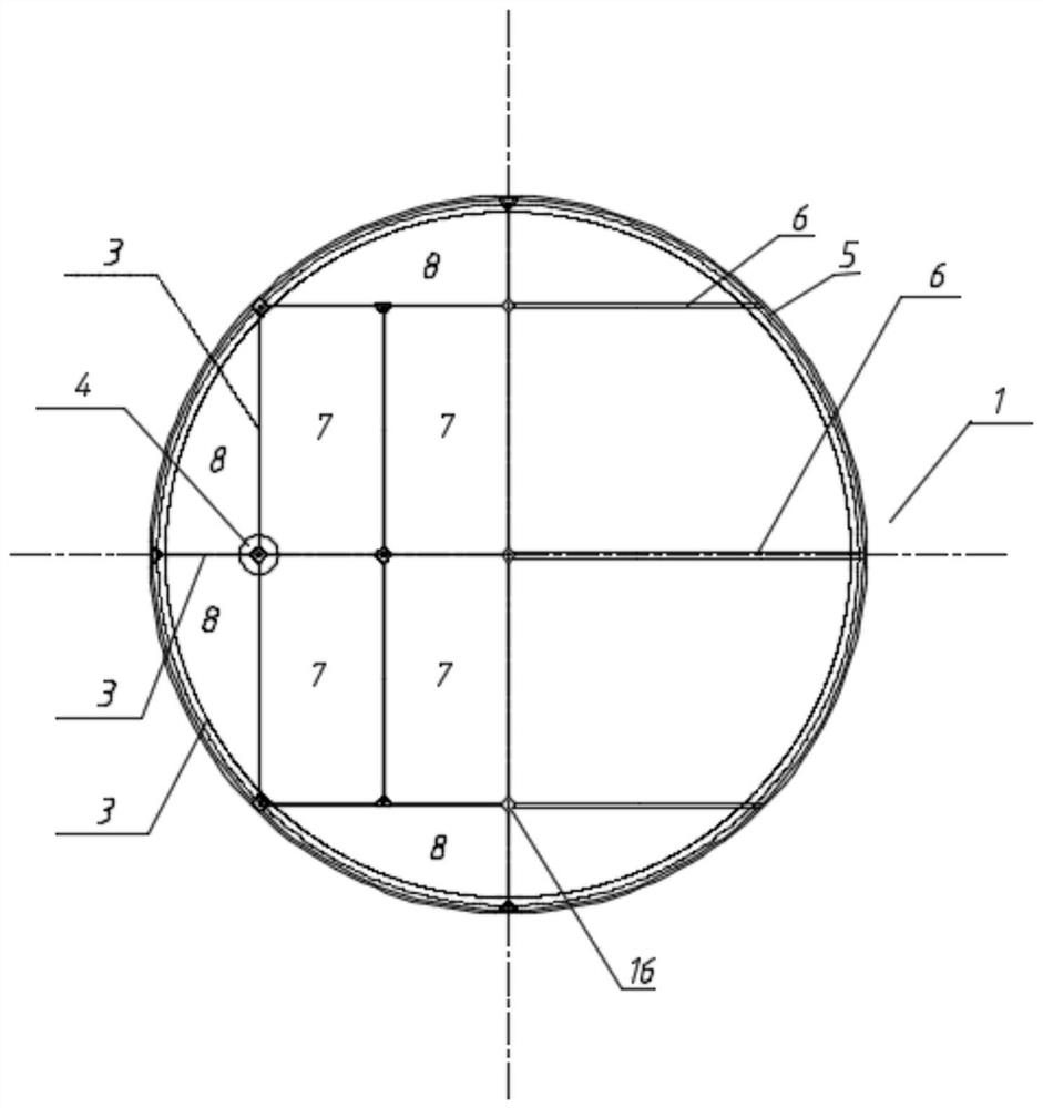
[0040] see Figure 1 to Figure 6 , a structure of a through-flow profile tray 1, including a rectangular tray sub-block 7 and an arc-shaped tray sub-block 8, a plurality of rectangular tray sub-blocks 7 and arc-shaped tray sub-blocks 8 are fixedly connected to the upper side of the support beam 6 and The inner area of ​​the support ring 5 is assembled horizontally to form a tray.

[0041] In this embodiment, the support ring 5 is circular, and the area adjacent to the support ring 5 is assembled with arc-shaped tray sub-blocks 8 , and other areas are assembled with rectangular tray sub-blocks 7 .

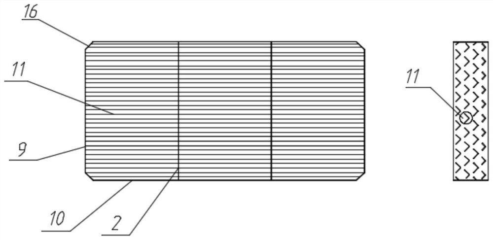
[0042]The sub-block of the tower plate includes a side plate 3, a support plate 2 and an angle profile 11. A plurality of side plates 3 are connected in a closed loop. The end is arranged on the inner side of the side plate 3. In the vertical direction, there are multi-layered corner profiles 11 arranged in a stepped manner. The vertical spacing between two adjacent layers of corn...

Embodiment 2

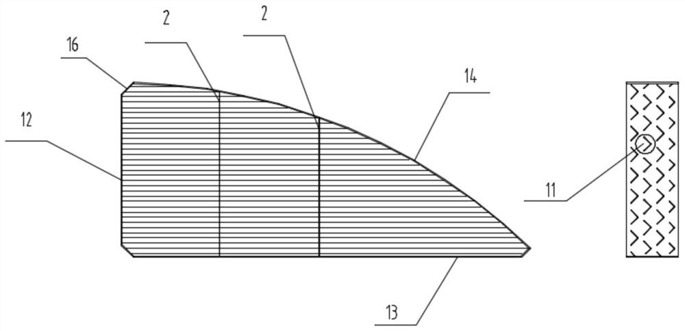
[0050] Such as Figure 7 As shown, the difference between this embodiment and Embodiment 1 is that in the sub-block of the tray, the size of the uppermost profile is 0.5 to 0.8 times that of the other layers, so that the horizontal gap between the uppermost adjacent two profiles is larger than other profiles. The horizontal gap between two adjacent profiles on the top layer is the defoaming structure; the horizontal gap between the other layers of profiles ensures full contact between gas and liquid, and the horizontal gap between the top layer of profiles When the gas velocity increases, the gas velocity decreases, and the impurities and liquid droplets flow to the lower layer under the action of gravity to play the role of defoaming; this defoaming structure is a part of the structure of the tray itself, which has dual functions of separation and defoaming, and no additional installation is required. Demister, and each tray has a demister function, the demister efficiency is...


PUM


Abstract

The invention relates to a structure and an installation method of a flow-through type profile tower plate. The structure comprises a supporting ring, a supporting beam and tower plate sub-blocks assembled in the supporting ring, each tower plate sub-block comprises a side plate, a supporting plate and a plurality of layers of sectional materials in the vertical direction, and a plurality of sectional materials are arranged on each layer in the horizontal direction. The sectional materials penetrate through the holes formed in the supporting plate, the two ends of the sectional materials are inserted into the holes formed in the side plate, the contact positions of the sectional materials and the holes are fixed through spot welding, tower plate sub-blocks are formed, the holes in the supporting plates and the holes in the side plates provide supporting and limiting for the sectional materials, the installation precision of the sectional materials is improved, the supporting plate and the side plate can also serve as tower plate supporting beams, and the structural strength of the tower plate is improved. The corners of the adjacent tower plate sub-blocks enclose to form a complete buckling groove, the tower plate sub-blocks are buckled through pressing plates, the pressing plates are provided with connecting holes corresponding to the buckling grooves, the supporting beams and the supporting rings are provided with positioning holes corresponding to the buckling grooves, and the tower plate sub-blocks are fixed by inserting fixing bolts, so that the tower plate is mounted, the displacement of the tower plate is limited, and the tower plate is convenient to dismount.

Description

technical field [0001] The invention belongs to the field of tower internals, and relates to a structure and an installation method of a flow-through profile tray. Background technique [0002] The through-flow tray is a gas-liquid counter-flow tray without a downcomer. The gas is from bottom to top, and the liquid is in contact with the tray gap from top to bottom. Among them, the cross-flow angle profile tray has a simple structure and good anti-blocking effect , with large processing capacity and low cost, it is widely used in unit operations such as rectification and absorption in engineering. The gas-liquid contact channel of the through-flow multi-layer stepped corner profile tray is determined by the horizontal and vertical distances of the upper and lower adjacent corner profiles and the fixed angle of the corner profiles. Therefore, the corner profiles are required to be evenly arranged in the horizontal and vertical directions , the installation angles of the corn...

Claims


Application Information

Patent Timeline
Patent Type & Authority Applications(China)
IPC IPC(8): B01D3/32B01D19/00B01D53/18
CPCB01D3/324B01D19/0073B01D53/18
Inventor 吴嘉
Owner CHONGQING GREEN FINE TECH CO LTD
Why Eureka
Try Eureka