Diode copper sheet bending machine
A bending machine and diode technology, applied in the field of mechanical processing, can solve the problems of low bending efficiency and low degree of automation, and achieve the effect of high production efficiency and high degree of automation
- Summary
- Abstract
- Description
- Claims
- Application Information
AI Technical Summary
Problems solved by technology
Method used
Image

Examples
Embodiment Construction
[0016] The following will clearly and completely describe the technical solutions in the embodiments of the present invention with reference to the accompanying drawings in the embodiments of the present invention. Obviously, the described embodiments are only some, not all, embodiments of the present invention. Based on the embodiments of the present invention, all other embodiments obtained by persons of ordinary skill in the art without making creative efforts belong to the protection scope of the present invention.
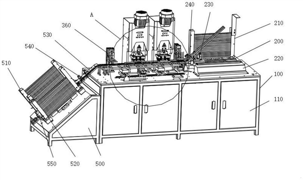
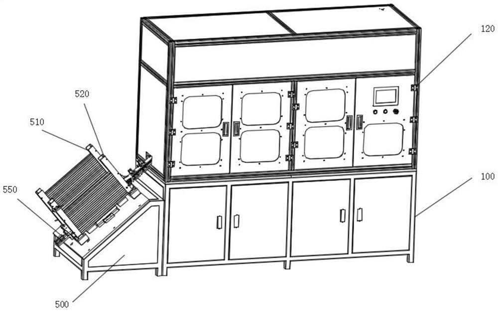
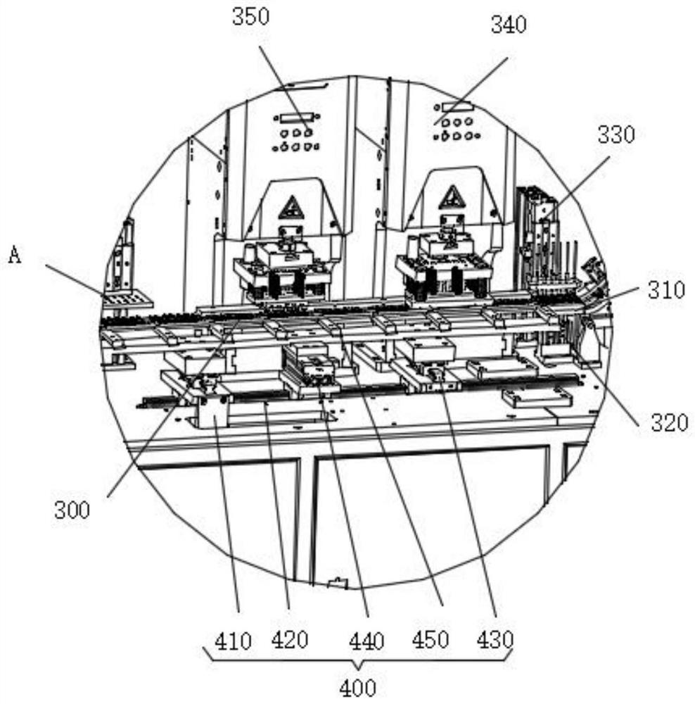
[0017] The invention provides a diode copper sheet bending machine, which has a high degree of automation, does not need manual operation, can simultaneously bend multiple diodes, and has high production efficiency. Please refer to Figure 1-3 , including a first box body 100, a material distribution mechanism 200, a material delivery track 300, a fork delivery mechanism 400 and a connecting box body 500;
[0018] see again Figure 1-3 , the first box 100 is ...
PUM
 Abstract
Description
Claims
Application Information
 - R&D
- Intellectual Property
- Life Sciences
- Materials
- Tech Scout
- Unparalleled Data Quality
- Higher Quality Content
- 60% Fewer Hallucinations
Browse by: Latest US Patents, China's latest patents, Technical Efficacy Thesaurus, Application Domain, Technology Topic, Popular Technical Reports.
© 2025 PatSnap. All rights reserved.Legal|Privacy policy|Modern Slavery Act Transparency Statement|Sitemap|About US| Contact US: help@patsnap.com