
Clamping mechanism and clamping device

A technology of clamping mechanism and clamping parts, which is applied in the direction of workpiece clamping device, positioning device, clamping, etc., and can solve the problems of complex structure of clamping device, complex structure of clamping mechanism, low efficiency of clamping and releasing operations, etc. , to achieve the effect of improving the efficiency of clamping and releasing operations, saving layout space, and simple structure

Active Publication Date: 2022-02-01
TONGJI UNIV
View PDF6 Cites 3 Cited by
  • Summary
  • Abstract
  • Description
  • Claims
  • Application Information

AI Technical Summary

Problems solved by technology

[0004] The object of the present invention is to provide a clamping mechanism to solve the problems of the current clamping mechanism with complex structure and low clamping and releasing operation efficiency; The object of the invention is also to provide a clamping device to solve the problems that the current clamping device has a relatively complicated structure and low efficiency of clamping and releasing operations

Method used


Image

  • Clamping mechanism and clamping device
  • Clamping mechanism and clamping device
  • Clamping mechanism and clamping device

Examples


Embodiment 1

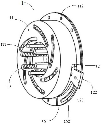
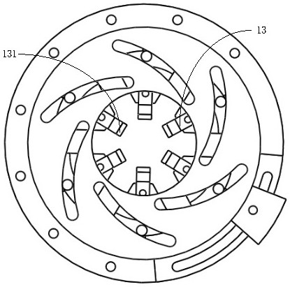
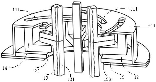
[0065] Such as figure 1 , figure 2 As shown, the clamping mechanism includes a fixed base 15. The fixed base 15 is provided with a guide seat 12 and a dial 11. The guide seat 12 is provided with clamping jaws distributed along the circumference. The radial guides of the circumference of each clamping jaw are assembled on On the guide seat 12, in this embodiment, the fixed base 15 is a bottom cover plate.

[0066] Such as image 3 , Figure 6 As shown, the dial 11 is a cover structure with a cylindrical circumferential side wall, the side of the dial 11 facing the bottom cover is an opening, the edge of the opening is provided with a flange, and the flange is provided with a flange The hole 112 is used for fixed connection with the bottom cover, so that the dial 11 is fixed on the bottom cover, and the bottom cover covers the opening side of the cover structure. The dial 11 has a through dial center hole 114 , and the dial center hole 114 runs through the dial surface of t...

Embodiment 2

[0081] The difference between this embodiment and embodiment 1 is that the clamping surface of the clamping head of the jaw in embodiment 1 is a plane, and in this embodiment, as Figure 10 As shown, the clamping surface of the clamping head 13 of the jaws is an arc surface. After each jaw clamps the clamped part, the clamping surface of each jaw forms a circle to adapt to the clamping of the cylindrical rod.

Embodiment 3

[0083] The difference between this embodiment and embodiment 1 is that the clamping surface of the jaws in embodiment 1 is a plane, and the structure of each jaw is the same, and in this embodiment, such as Figure 11 and Figure 12 As shown, the clamping mechanism is used to clamp a square bar, and the structure of each clamping jaw is different. The clamping mechanism includes an edge clamping jaw for clamping the edge of the clamped piece and a clamping jaw for clamping the clamped piece. For the side jaws on the side, the clamping surface of the chuck of the side jaws is a plane, and the clamping surface of the chuck of the edge jaws is an L-shaped surface.


PUM


Abstract

The invention relates to a clamping mechanism and a clamping device. The clamping mechanism comprises a fixed base body, the fixed base body is provided with a guide base and a driving plate, the guide base is provided with clamping jaws distributed along the circumference, the clamping jaws are assembled on the guide base in a guiding mode in the radial direction of the circumference, and the fixed base body, the guide base and the driving plate are provided with center holes for a clamped part to penetrate through. The clamping jaw is provided with a poking column, the driving plate is provided with a poking groove, the poking column is arranged in the poking groove in a guiding mode in the extending direction of the poking groove and can rotate in the poking groove, the distance between each point in the extending direction of the poking groove and the circle center of the circumference is gradually changed, and one of the guide base and the driving plate is fixedly assembled on the fixed base body. The other one of the guide base and the driving plate is rotationally assembled on the fixed base body, so that when the guide base and the driving plate rotate relatively, the clamping jaws stretch and retract in the radial direction to clamp and release a clamped piece by means of the guide movement of the drive column in the drive groove, and the whole clamping mechanism is simple in structure, convenient to manufacture and low in cost.

Description

technical field [0001] The invention relates to a clamping mechanism and a clamping device. Background technique [0002] For rod-shaped objects, a three-jaw chuck is usually used for clamping. The three-jaw chuck includes a fixed base. The fixed base is provided with a guide seat and a dial. There are three jaws distributed along the circumference of the guide seat. Each jaw is assembled on the guide seat along the radial direction of its circumference. The dial is composed of The disc body provided with plane threads is formed, and the clamping jaws are provided with driving threads adapted to the plane threads on the turntable. When the turntable rotates, the turntable can drive the three jaws to expand and contract in the radial direction through thread transmission, so as to realize the clamping and releasing of the workpiece, so that the three-jaw chuck can form a large clamping force, and can also clamp circular and triangular shapes. Workpieces of different shapes,...

Claims


Application Information

Patent Timeline
Patent Type & Authority Applications(China)
IPC IPC(8): B23Q3/06B25B11/00
CPCB23Q3/06B25B11/00
Inventor 汤奇荣陈心怡徐鹏杰
Owner TONGJI UNIV
Learn More