A state detection device for substation power equipment with diagnostic function
A technology of state detection device and current detection device, which is applied in the direction of measuring device, electrical equipment structural parts, measuring current/voltage, etc., which can solve the deviation of detection results, inconvenient operation, and the inability of staff to grasp electrical equipment well, etc. question
Active Publication Date: 2022-03-11
山东广域科技有限责任公司
View PDF9 Cites 0 Cited by
- Summary
- Abstract
- Description
- Claims
- Application Information
AI Technical Summary
Problems solved by technology
The operating environment of today's power equipment is complex, and it is extremely easy to receive external interference during testing, which leads to deviations in test results, and the staff cannot grasp the specific conditions of the power equipment well; the detection devices are generally fixed on the power equipment by screws. If a problem occurs, it needs to be disassembled, which is inconvenient to operate. The Chinese invention patent with the publication number CN108645443A discloses an online digital state detection device for electric equipment, including a cabinet body. The storage cavity is slidably connected with a pull-out assembly, and the bottom wall of the storage cavity is provided with a guide chute, and the top end is slidably-fitted in the guide chute, and is fixedly matched with the bottom end surface of the draw-draw assembly. The connected guide slider, the inner thread of the guide slider is connected with the first screw extending forward and backward, and the rear end of the first screw is power-fitted with the drive motor fixed in the rear inner wall of the guide chute connected, the inner wall on the right side of the storage cavity communicates with a sinking groove, the cabinet on the right side of the sinking groove is provided with a first cavity, and the first cavity is connected to the sinking groove The part between is communicated with a first chute, the cabinet below the first chute is provided with a second cavity, and the part between the second cavity and the first chute The internal connection is provided with a through groove to detect the power equipment, but this device cannot be installed on the transformer for real-time detection. The device of the present invention can be installed on the power equipment for real-time detection and can cool down the internal temperature
Method used
View moreImage
Smart ImageViewing Examples
Examples
Embodiment
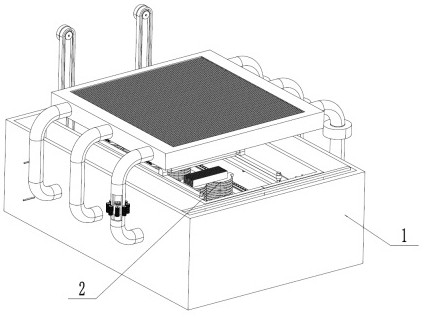
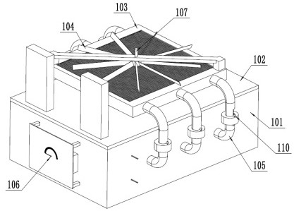
[0023] Example: Reference figure 1 A kind of power equipment state detection device with diagnostic function shown in the substation includes a cooling device 1 that cools the device of the present invention through liquid and a fan when the device of the present invention is working. state of the current sensing device 2.
Login to View More PUM
 Abstract
The invention discloses a power equipment status detection device for a substation with a diagnostic function, relates to the technical field of power equipment detection, and includes a cooling device for cooling the device of the invention through a liquid and a fan when the device of the invention is working. The cooling device is provided with a The water pump and the bulb, when the liquid flows, the bulb is always on, and the side of the heat sink is equipped with a current indicator plate, which is convenient for workers to judge the fault. The inside of the heat sink is equipped with a current detection device to detect the current state of the internal transformer module. There are two rotating motors inside, and the rotating motors drive the detection head to move in the current detection device, and the detection head detects the transformer modules with different coil numbers. The device of the present invention can directly install the device of the present invention on the transformer module , for a long time to detect and through the setting of the cooling device, there is no need to worry about the situation of excessive temperature.
Description
technical field [0001] The invention relates to the technical field of power equipment detection, in particular to a power equipment state detection device for a substation with a diagnosis function. Background technique [0002] Electric power equipment testing device refers to the equipment for test, verification, detection and acceptance of electric power production and grid operation, which provides reliable guarantee for the safety and reliability of electric power operation. The operating environment of today's power equipment is complex, and it is extremely easy to receive external interference during testing, which leads to deviations in test results, and the staff cannot grasp the specific conditions of the power equipment well; the detection devices are generally fixed on the power equipment by screws. If a problem occurs, it needs to be disassembled, which is inconvenient to operate. The Chinese invention patent with the publication number CN108645443A discloses a...
Claims
Login to View More Application Information
Patent Timeline
 Patent Type & Authority Patents(China)
IPC IPC(8): G01R31/00G01R19/00G01R1/02H05K7/20
CPCG01R31/00G01R19/0092G01R1/02H05K7/20218H05K7/20136H05K7/2039
Inventor 戴吉勇孟宾张勇孙建瑞刘书圻李保原侯梦琪平金明苏彬郭守席
Owner 山东广域科技有限责任公司
Features
- R&D
- Intellectual Property
- Life Sciences
- Materials
- Tech Scout
- Unparalleled Data Quality
- Higher Quality Content
- 60% Fewer Hallucinations
Learn More Browse by: Latest US Patents, China's latest patents, Technical Efficacy Thesaurus, Application Domain, Technology Topic, Popular Technical Reports.
© 2025 PatSnap. All rights reserved.Legal|Privacy policy|Modern Slavery Act Transparency Statement|Sitemap|About US| Contact US: help@patsnap.com


