Cable trench cover plate laying device and method

A cable trench cover and laying device technology, which is applied in the direction of cable installation, ground cable installation, cable laying equipment, etc., can solve the problems of low laying efficiency, achieve efficient laying, save manpower, and improve laying efficiency.

Pending Publication Date: 2022-02-01
国网河南省电力公司镇平县供电公司
View PDF2 Cites 1 Cited by
  • Summary
  • Abstract
  • Description
  • Claims
  • Application Information

AI Technical Summary

Problems solved by technology

This invention can only complete the installation, lifting and laying of one cover plate at a time. Although it saves manpower, the laying efficiency is still low, and the above technical problems cannot be solved.

Method used


Image

  • Cable trench cover plate laying device and method
  • Cable trench cover plate laying device and method
  • Cable trench cover plate laying device and method

Examples


Embodiment 1

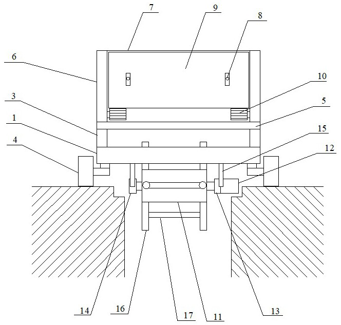
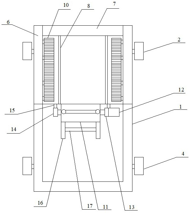
[0033] Such as Figure 1~3 As shown, a cable trench cover laying device includes a drive frame, a storage mechanism for placing a plurality of cable trench covers arranged on the drive frame, and a storage mechanism arranged on one side of the storage mechanism Pushing mechanism, and the discharging mechanism that is arranged on the lower side of the storage mechanism; the driving frame includes a bottom frame 1, driving rollers 2 and a plurality of support rods 3, and the front side of the bottom frame 1 is provided with two The driving roller 2 is described, and two rollers 4 are arranged on the rear side of the bottom frame 1 , and the storage mechanism is connected to the bottom frame 1 through a plurality of support rods 3 .

[0034] The storage mechanism includes a base plate 5, a limiting plate 6 arranged on the left and right sides of the base plate 5, and a positioning plate 7 arranged on the front side of the base plate 5, and two positioning rods 8 are arranged on t...

Embodiment 2

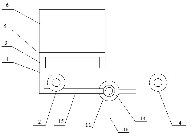
[0040] Such as Figure 4 As shown, the cable trench cover laying device of the embodiment of the present invention, as a further improvement of the first embodiment, differs from the first embodiment in that:

[0041] Two screw holes are arranged on the positioning plate, external threads are provided at one end of the two positioning rods, and the two positioning rods are threadedly connected with the positioning plate.

[0042] The two driving rollers and the two rollers are respectively connected to the bottom frame through a shock absorber.

[0043] The shock absorber includes a base block 18, two springs and two connectors, the first connector 19 is fixed on the bottom frame, and a hydraulic rod 20 is arranged at the bottom of the first connector 19, and the lower end of the hydraulic rod 20 is connected to the base block 18. The top surface is fixedly connected, the hydraulic rod 20 is sleeved with a first spring 21; the base block 18 is provided with a transverse throu...

Embodiment 3

[0045] A cable trench cover laying method, comprising the following steps:

[0046] Step 1: The cable trench cover laying device is placed at one end of the cable trench, and spans the cable trench, and the lower half of the feeding mechanism is located in the cable trench;

[0047] Step 2: A batch of cable trench cover plates are placed vertically in the storage mechanism, and the two positioning rods pass through the through holes on the cable trench cover plate and are connected with the positioning plate;

[0048] Step 3: The cable trench cover walks to the other end of the cable trench under the action of the driving frame, and simultaneously starts the two crawler wheels of the pushing mechanism and the motor of the discharging mechanism;

[0049] Step 4: Driven by the stepping motor, the two crawler wheels of the pushing mechanism rotate at a certain angle each time, so that the outer cable trench cover plate falls off from the two positioning rods and falls on one of t...


PUM


Abstract

The invention discloses a cable trench cover plate laying device and method, and belongs to the technical field of cable trench cover plate laying. The cable trench cover plate laying device comprises: a driving frame, a material storage mechanism which is arranged on the driving frame and is used for placing a plurality of cable trench cover plates, a material pushing mechanism which is arranged on one side of the material storage mechanism, and a discharging mechanism which is arranged on the lower side of the storage mechanism. The driving frame comprises a bottom frame, driving rollers and a plurality of supporting rods, the two driving rollers are arranged on the front side of the bottom frame, the two rollers are arranged on the rear side of the bottom frame, and the material storage mechanism is connected to the bottom frame through the supporting rods. The cable trench cover plate laying device can stably and efficiently lay cable trench cover plates, and manpower is saved.

Description

technical field [0001] The invention relates to the technical field of cable trench cover laying, in particular to a cable trench cover laying device and method. Background technique [0002] The cable trench is an underground passage for laying and replacing electric power or telecommunication cable facilities. After the internal cables are laid, a cover plate needs to be laid on it for sealing. The existing cable trench cover plates include cement cover plates and composite material cover plates. There are two through holes on the cover plate. The laying workers insert their fingers into the through holes, and place the cover plates one by one in the grooves on the upper side of the cable trench. However, due to the long length of the cable trench and the heavy weight of the cable trench cover plate, laying by manpower not only consumes a lot of manpower, but also has low laying efficiency. [0003] Publication No. CN 111371056 A patent document discloses a cable trench c...

Claims


Application Information

Patent Timeline
Patent Type & Authority Applications(China)
IPC IPC(8): H02G9/02H02G1/06
CPCH02G9/02H02G1/06
Inventor 鲁萍
Owner 国网河南省电力公司镇平县供电公司
Why Eureka
Try Eureka