Electric tool with motor stator and motor rotor intelligently controlled through circuit board

A technology for electric tools and motor stators, which is applied in the direction of controlling mechanical energy, connecting with control/drive circuits, and electric components. It can solve problems such as difficult to guarantee safety and reliability, low motor torque performance, and sparks from carbon brushes. Cooling effect, stable operation and prolonging service life

Pending Publication Date: 2022-02-01
苏州力森工具科技有限公司
View PDF2 Cites 0 Cited by
  • Summary
  • Abstract
  • Description
  • Claims
  • Application Information

AI Technical Summary

Problems solved by technology

[0003] Due to the rotation of the rotor, there is always contact friction between the carbon brush and the commutation ring. Therefore, in the long-term relative rotation, the carbon brush is accompanied by wear and tear, resulting in uneven contact surface with the commutation ring, insufficient carbon brush pressure and other conditions. Brushes are often accompanied by sparks; at the same time, most of the current motors use magnetic rings. The torque performance of the motors made in this way is relatively low. At the same time, magnetic interference will affect the electronic components on the power tool, and it is also prone to iron sticking. chip phenomenon, safety and reliability are difficult to guarantee

Method used


Image

  • Electric tool with motor stator and motor rotor intelligently controlled through circuit board
  • Electric tool with motor stator and motor rotor intelligently controlled through circuit board

Examples


Embodiment Construction

[0019] The following will clearly and completely describe the technical solutions in the embodiments of the present invention with reference to the accompanying drawings in the embodiments of the present invention. Obviously, the described embodiments are only some, not all, embodiments of the present invention. Based on the embodiments of the present invention, all other embodiments obtained by persons of ordinary skill in the art without making creative efforts belong to the protection scope of the present invention.

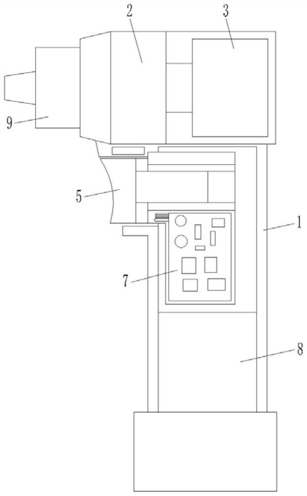
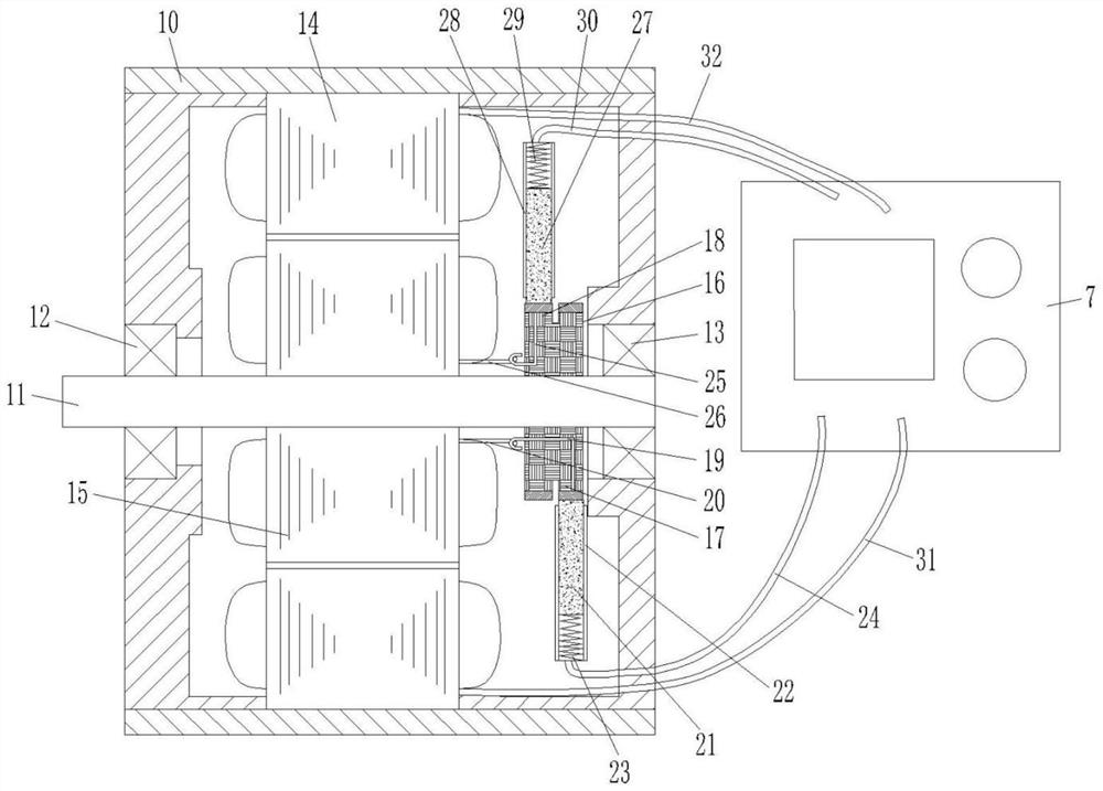
[0020] see figure 1 , 2 As shown, the present invention provides a technical solution: an electric tool that intelligently controls the motor stator and rotor through a circuit board, including an electric tool housing 1 and a motor provided in the electric tool housing 1 for providing driving force 3. The end of the electric tool housing 1 is provided with a transmission mechanism 2, one end of the transmission mechanism 2 is fixedly connected to the motor s...


PUM


Abstract

The invention discloses an electric tool with a motor stator and a motor rotor intelligently controlled through a circuit board, which comprises an electric tool shell and a motor arranged in the electric tool shell and used for providing a driving force, and a transmission mechanism is arranged at the end part of the electric tool shell. One end of the transmission mechanism is fixedly connected with a motor shaft of the motor, a tool head is installed at the other end of the transmission mechanism, a switch is arranged on the electric tool shell, a circuit board is arranged in the electric tool shell, and the circuit board is electrically connected with the motor and the switch. The electric tool is characterized in that a power supply of a rotor of the motor for providing rotary motion power is controlled by a circuit board, a fixed magnetic field is generated after a winding of the rotor is electrified, and a rotary magnetic field is generated by a stator controlled by the circuit board; the rotor is controlled by the circuit board to form a rotating magnetic field, rare earth magnetic tiles do not need to be installed on the rotor, a large number of rare earth permanent magnet materials can be saved, cost is greatly saved, and meanwhile the rare earth magnetic tiles are prevented from adsorbing scrap iron.

Description

technical field [0001] The invention relates to the technical field of electric motors, in particular to an electric tool which intelligently controls a motor stator and rotor through a circuit board. Background technique [0002] Motors are used in tools in various fields of life. The motors on many tools must have the function of forward and reverse rotation when in use, especially the electric drill or hammer tools used. Therefore, a reversing device will be installed in the motor. The device is composed of a brush and a commutation ring; most of the brushes are carbon brushes, and the carbon brush is mainly used to introduce the rotor current required by the motor operation into the rotor coil through the connection with the commutation ring, provide excitation power, and then transmit it to the rotor , the rotor of the motor is equivalent to a rotating magnet, and the commutation task of the motor is realized through carbon brushes. [0003] Due to the rotation of the ...

Claims


Application Information

Patent Timeline
Patent Type & Authority Applications(China)
IPC IPC(8): H02K11/30H02K7/10H02K7/14H02K13/10H02K9/28
CPCH02K11/30H02K7/10H02K7/14H02K13/10H02K9/28
Inventor 刘双凤赵东宏
Owner 苏州力森工具科技有限公司
Why Eureka
Try Eureka