Side comb plate mechanism of crusher, and crusher

A technology of crushers and combs, which is applied in the field of side comb mechanisms and crushers, can solve the problems of material accumulation and unsmooth discharge, and achieve the effect of preventing material accumulation, preventing effect, and avoiding material accumulation

Pending Publication Date: 2022-02-08
SID MACHINERY BEIJING
View PDF0 Cites 1 Cited by
  • Summary
  • Abstract
  • Description
  • Claims
  • Application Information

AI Technical Summary

Problems solved by technology

[0004] The technical problem solved by the present invention is to provide a side comb mechanism of the crusher and the crusher, which can prevent materials from entering the corner of the crushing box through the inner wall of the side comb, effectively solving the problems of material accumulation and unsmooth discharge

Method used


Image

  • Side comb plate mechanism of crusher, and crusher
  • Side comb plate mechanism of crusher, and crusher
  • Side comb plate mechanism of crusher, and crusher

Examples


Embodiment 1

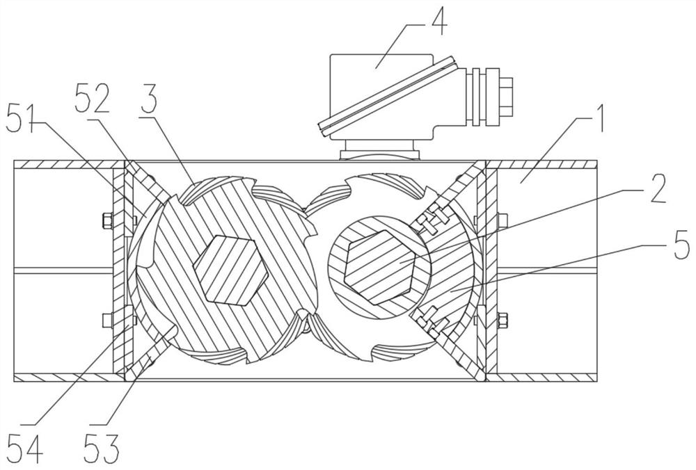
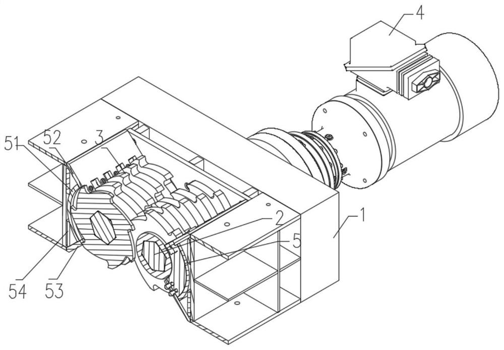
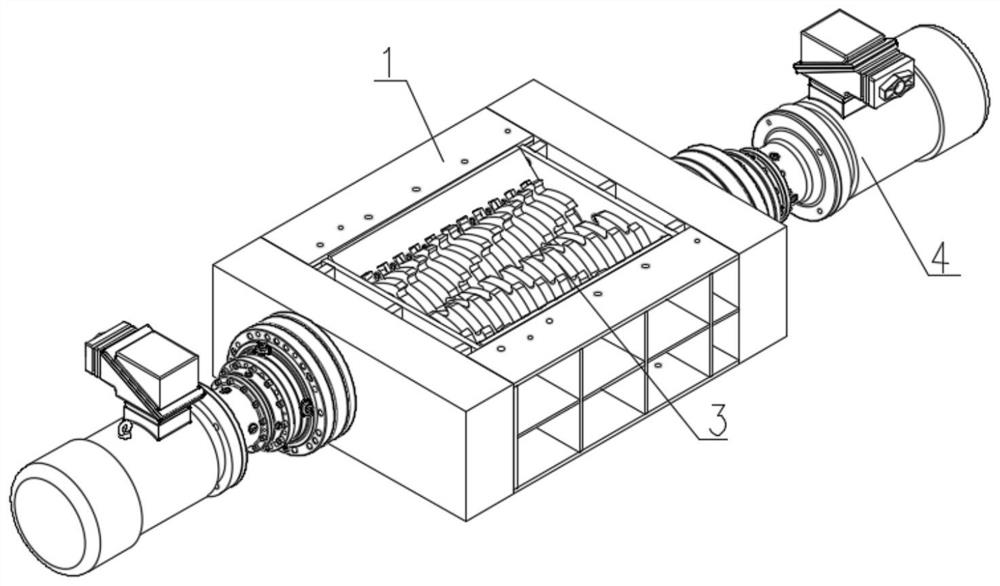
[0058] Such as figure 1 , 2 , 3, the crusher described in this embodiment includes:

[0059] broken box 1,

[0060] The cutter shaft 2 is arranged in the crushing box 1;

[0061] A plurality of cutters 3 are arranged on the cutter shaft 2;

[0062] a driving part 4, used to drive the rotation of the cutter shaft 2;

[0063] The side comb mechanism 5 of the crusher is arranged on the inner wall of the side wall of the crushing box 1, and includes an installation part connected to the inner wall of the crushing box and a plurality of combs sequentially arranged on the inner wall of the installation part;

[0064] Such as Figure 4 As shown, the installation part includes: a wall plate 51, an upper cover plate 52, a lower cover plate 53 and a mounting plate 54. The inner wall of the wall plate 51 is adapted to the orbit of the cutter 3 of the crusher, and the inner wall of the wall plate 51 is compatible with the There is a predetermined gap between the trajectories of the...

Embodiment 2

[0069] This embodiment provides another implementation of the side comb mechanism.

[0070] The rest of the structure of the side comb mechanism of the crusher is the same as that of Embodiment 1, the difference being:

[0071] The cross-section of the wall plate 51 is a multi-segment linear shape approaching the arc shape, the center of the arc shape is located on the side where the comb plate is located, and the circle where the arc shape is located is related to the rotation of the head of the cutter of the crusher. The trajectory is a concentric circle, and the radius of the circle where the arc is located is slightly larger than the radius of the turning trajectory of the head of the crusher cutter.

[0072] Specifically, the polyline can be Figure 5 The 3 line segments shown connect; Image 6 The 4 line segments shown connect; Figure 7 The 5 line segments shown connect and so on. Specifically, the multi-segment line shape can be formed by continuous welding of mult...

Embodiment 3

[0075] In this embodiment, the cutter 3 is a two-way cutter, and there is a preset gap between the cutter 3 and the adjacent comb plate 55, so that the cutter 3 of the crusher forms a shearing structure with the mounting part or the adjacent comb plate 55 , that is, the cutter 3 is a moving knife, and the comb plate 55 or the upper cover plate 52 and the lower cover plate 53 of the installation portion are stationary fixed knives, specifically the top edge of the comb plate 55 or the upper cover plate 52 and the lower cover plate 53 The two sides of the side edge form a moving and fixed knife shearing structure, which increases auxiliary crushing for the crusher and improves the crushing capacity of the crusher.


PUM


Abstract

The invention provides a side comb plate mechanism of a crusher, and the crusher. The side comb plate mechanism comprises: a mounting part, which is located on the inner wall of a crushing box of the crusher, wherein the mounting part is provided with an inner wall that is matched with the rotary operation track of cutters of the crusher, so when the cutters of the crusher rotate, the inner wall of the mounting part prevents materials from entering the corner parts of the crushing box; and a plurality of comb plates, which are sequentially arranged on the inner wall of the mounting part, wherein gaps between the comb plates are suitable for containing the cutters of the crusher to rotate and operate. According to the side comb plate mechanism of the crusher and the crusher, the materials are prevented from entering the corners of the crushing box through the inner walls of the side comb plates, and the problems of material accumulation and unsmooth discharging are effectively solved.

Description

technical field [0001] The invention belongs to the technical field of crushers, and in particular relates to a side comb mechanism of a crusher and the crusher. Background technique [0002] At present, the pretreatment of solid waste is usually completed using a crusher, for example, a rotary shear crusher is used to crush the solid waste. The rotary shear crusher is usually composed of a crushing box, a knife shaft, a knife, and a driving mechanism. The material entering the crushing box of the crusher is grabbed by the knife on the knife shaft and enters between adjacent knives. Through the relative rotation between the knives Shear the material, and the sheared material is discharged through the lower part of the crusher as the rotor continues to rotate. [0003] When the crusher is running, the material is cut and torn by the cutter of the crusher, and is brought to the lower part of the crusher by the cutter teeth. In order to reduce the material being brought back t...

Claims


Application Information

Patent Timeline
Patent Type & Authority Applications(China)
IPC IPC(8): B02C18/16B09B3/35
CPCB02C18/16B09B3/00B02C2018/162B02C2201/06
Inventor 王广民张兴乐皮尔让·夏尔诺
Owner SID MACHINERY BEIJING
Why Eureka
Try Eureka