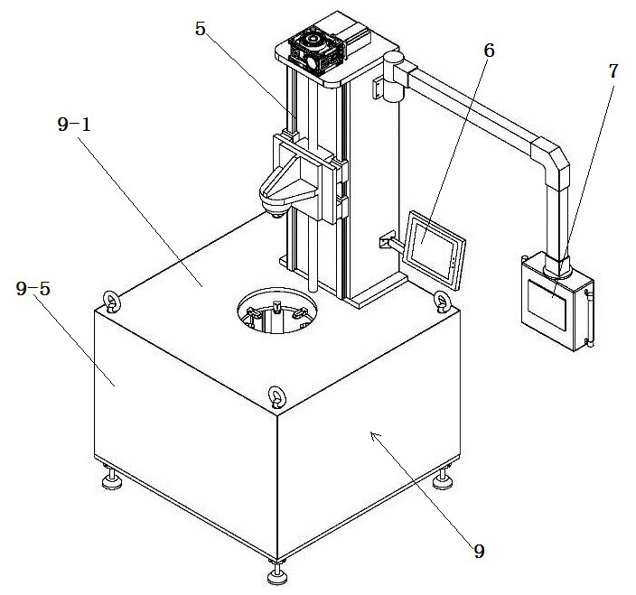
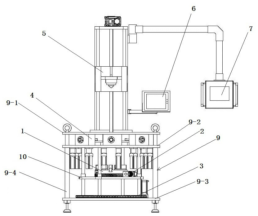
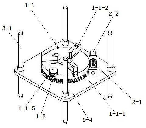
Automatic riveting equipment

A technology of riveting and pressing equipment, applied in metal processing equipment, feeding device, positioning device and other directions, can solve the problems of high manufacturing cost and complex structure, and achieve the effects of low cost, wide application range and simple structure

Pending Publication Date: 2022-02-08
PINGGAO GRP +2
View PDF1 Cites 2 Cited by
  • Summary
  • Abstract
  • Description
  • Claims
  • Application Information

AI Technical Summary

Problems solved by technology

[0004] In the above patent, in order to realize the riveting of 12 riveting points, there are twelve first riveting devices, and the first riveting device includes an oil cylinder and a pressure head, that is, a total of There are twelve oil cylinders and twelve pressure heads, not only the structure is very complicated, but also the manufacturing cost is very high
In addition, by controlling the actions of different oil cylinders, it is also possible to realize the riveting of 6, 4, 3 and 2 circumferentially evenly distributed riveting points, but for the riveting of other numbers of circumferentially uniformly distributed riveting points, the above patent It cannot be realized, and the riveting pressure of different numbers of circumferentially evenly distributed riveting points can only be satisfied by designing and manufacturing another set of riveting devices, resulting in higher manufacturing costs

Method used


Image

  • Automatic riveting equipment
  • Automatic riveting equipment
  • Automatic riveting equipment

Examples


Embodiment Construction

[0046] In order to make the object, technical solution and advantages of the present invention clearer, the present invention will be further described in detail below in conjunction with the accompanying drawings and embodiments. It should be understood that the specific embodiments described here are only used to explain the present invention, and are not intended to limit the present invention, that is, the described embodiments are only some of the embodiments of the present invention, but not all of the embodiments. The components of the embodiments of the invention generally described and illustrated in the figures herein may be arranged and designed in a variety of different configurations.

[0047] Accordingly, the following detailed description of the embodiments of the invention provided in the accompanying drawings is not intended to limit the scope of the claimed invention, but merely represents selected embodiments of the invention. Based on the embodiments of the...


PUM


Abstract

The invention provides automatic riveting equipment which comprises a rack, a workpiece positioning device and a workpiece riveting device. The workpiece positioning device is rotatably mounted on the rack and used for positioning a workpiece, and the workpiece riveting device comprises a riveting rod capable of moving telescopically and can apply pressure to the workpiece to be riveted. The automatic riveting equipment further comprises a rotary driving device in transmission fit with the workpiece positioning device, and the rotary driving device can drive the workpiece positioning device to rotate so that when a plurality of riveting points which are uniformly distributed on the circumference need to be riveted, a certain number of riveting points can be riveted through a riveting rod, and then the workpiece positioning device rotates by a certain angle; and the other riveting points can be riveted, namely, the workpiece positioning device can realize riveting of different numbers of circumferentially and uniformly distributed riveting points through intermittent rotation. Compared with the prior art, the riveting of different numbers of circumferentially and uniformly distributed riveting points can be realized without a plurality of sets of riveting devices so that the structure is simple, and the cost is relatively low.

Description

technical field [0001] The invention relates to the technical field of riveting equipment, in particular to an automatic riveting equipment. Background technique [0002] The ring riveting structure is composed of two inner and outer workpieces. The inner workpiece is provided with an annular groove. By applying a certain radial load to the outer workpiece, it is partially plastically deformed and embedded in the annular groove to hold it tightly. Internal workpieces are locked through structural interference. The existing riveting operation is to install the riveting tooling on the press machine. The riveting tooling includes two indenters, the upper and the lower. Therefore, only two points can be riveted at a time during riveting. If multi-point riveting is to be realized, an operator is required Performing multiple riveting operations, the workpiece needs to be continuously removed during the riveting process, and the workpiece is reinstalled after adjusting the angle, ...

Claims


Application Information

Patent Timeline
Patent Type & Authority Applications(China)
IPC IPC(8): B21D39/00B21D43/00
CPCB21D39/00B21D43/003
Inventor 宋继光李凯徐仲勋姜珊盼郝留成段晓辉刘恒王红超苗晓军司晓闯庞亚娟白玮高美金诸言涵
Owner PINGGAO GRP
Why Eureka
Try Eureka