Sealing element machining mechanism
A technology for processing mechanisms and seals, applied in metal processing equipment, manufacturing tools, grinding racks, etc., can solve the problems of unsuitable sealing rings for grinding devices, hindering grinding, and poor fixing effect of fixing mechanisms, etc., to achieve functionality Strong, increased friction, and easy cleaning of debris
- Summary
- Abstract
- Description
- Claims
- Application Information
AI Technical Summary
Problems solved by technology
Method used
Image

Examples
Embodiment 1
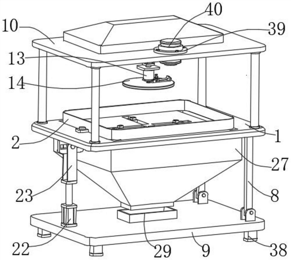
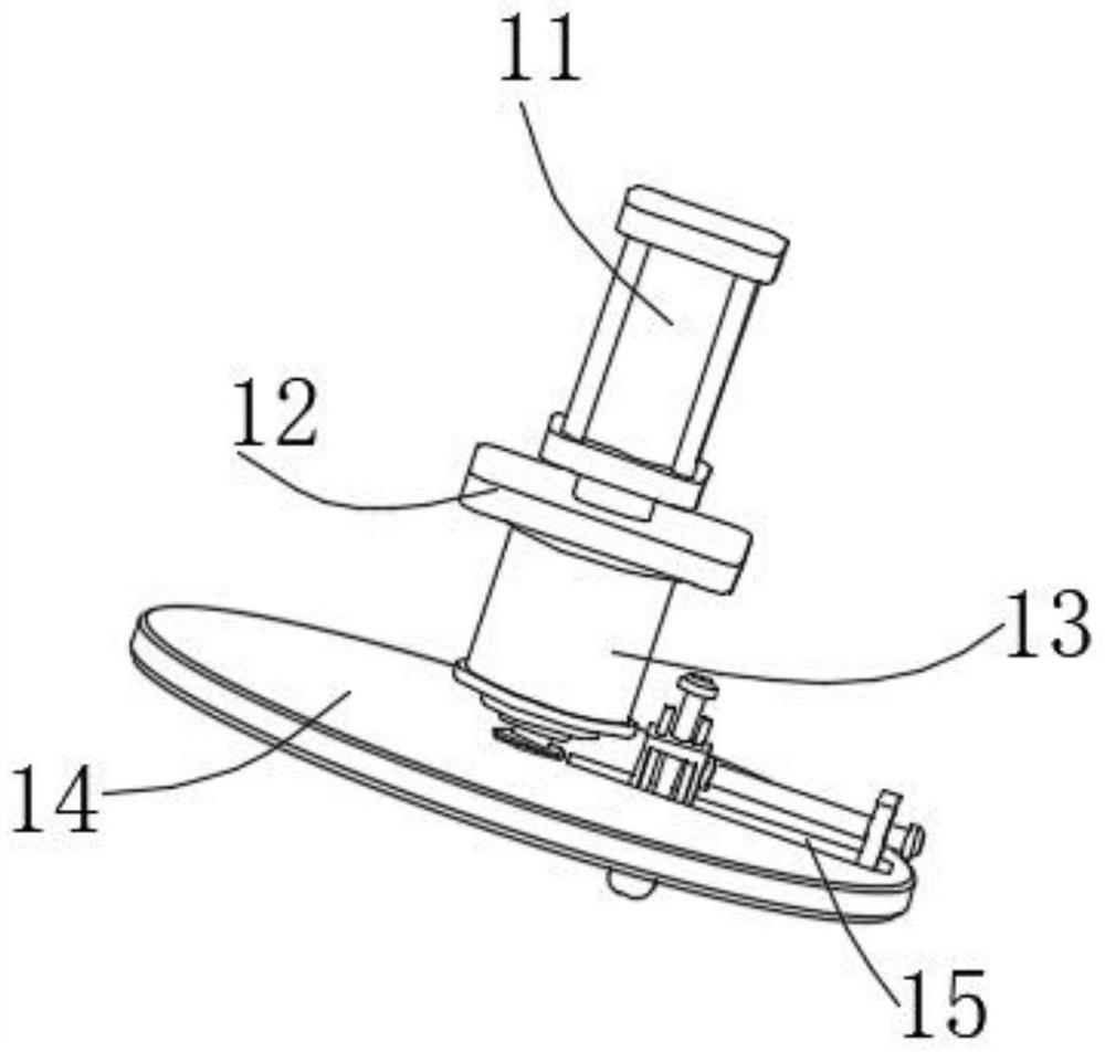
[0034] Such as figure 1 , figure 2 , image 3 , Figure 4 , Figure 5 , Figure 6 , Figure 7 , Figure 8 As shown, this embodiment proposes a seal processing mechanism, which includes a horizontally arranged table top 1, and a barrier frame 2 is horizontally arranged on the upper end of the table top 1. The barrier frame 2 prevents debris from flying out when the device is being polished, and is convenient for crushing. For the subsequent collection and cleaning of chips, the outer wall of the barrier frame 2 is fixedly installed with the installation block 3 horizontally. The installation block 3 is fixedly connected with the upper end surface of the table 1 through the bolt 4, and the bolt 4 is fixed to install the barrier frame 2, which makes the installation and disassembly of the barrier frame 2 more convenient. , the upper end surface of the table top 1 is provided with a through groove 37 through which debris can pass through and fall into the funnel groove 27 t...
Embodiment 2
[0036] The scheme in embodiment 1 is further introduced below in conjunction with specific working methods, see the following description for details:
[0037] Such as figure 1 , Figure 4 , Figure 6 , Figure 7 As shown, as a preferred embodiment, on the basis of the above-mentioned method, the angle adjustment mechanism includes a second electric push rod 22 that is vertically fixedly installed on the upper end surface of the bottom plate 9, and the upper end of the second electric push rod 22 is fixed and installed vertically. The drive plate 23 rotates the connected drive shaft 24 laterally, and a slotted plate 25 fixedly installed on the lower end surface of the table 1 is arranged horizontally above the second electric push rod 22, and a drive groove penetrating through the side wall of the slotted plate 25 is opened horizontally. 26. The drive shaft 24 moves through the drive groove 26. The collection mechanism includes a funnel groove 27 fixedly installed on the lo...
Embodiment 3
[0039] The schemes in Embodiment 1 and Embodiment 2 are further introduced below in conjunction with specific working methods, see the following description for details:
[0040] Such as figure 1 , image 3 , Figure 8 As shown, as a preferred embodiment, on the basis of the above method, the first adjustment mechanism includes an adjustment plate 30 vertically fixedly installed on the upper end surface of the grinding disc 14, and the side wall of the slider 16 close to the adjustment plate 30 is installed laterally. There is a first threaded rod 31 threaded through the adjustment plate 30, and the end of the first threaded rod 31 away from the slider 16 is fixedly installed with a first knob 32, and the second adjustment mechanism includes a second screw mounted on the upper end surface of the grinding block 17 for vertical rotation. Threaded rod 33, the thread of the second threaded rod 33 runs through the slide block 16 and the second knob 34 is fixedly installed on the ...
PUM
 Abstract
Description
Claims
Application Information
 - R&D Engineer
- R&D Manager
- IP Professional
- Industry Leading Data Capabilities
- Powerful AI technology
- Patent DNA Extraction
Browse by: Latest US Patents, China's latest patents, Technical Efficacy Thesaurus, Application Domain, Technology Topic.
© 2024 PatSnap. All rights reserved.Legal|Privacy policy|Modern Slavery Act Transparency Statement|Sitemap