Eureka AIR delivers breakthrough ideas for toughest innovation challenges, trusted by R&D personnel around the world.

Metal part polishing device

A technology of metal parts and grinding mechanism, which is applied in the direction of grinding drive device, grinding automatic control device, metal processing equipment, etc., which can solve the problems of human injury, difficulty in grinding, and insufficient efficiency, etc., so as to reduce re-use The effect of grinding, simple structure and simple device

Inactive Publication Date: 2022-02-08
王婷
View PDF0 Cites 1 Cited by
  • Summary
  • Abstract
  • Description
  • Claims
  • Application Information

AI Technical Summary

Problems solved by technology

[0002] At present, most of the grinding of metal parts is done manually, or the edges are polished by machines, while the holes of metal parts are still polished manually. If the metal parts are not polished, it is easy to cause harm to the installer, and the grinding is done manually. , It is easy to be injured for novices, and manual grinding takes a long time, the efficiency is low, and it is difficult to achieve complete grinding. The current manual and machine-assisted grinding is mostly to manually clamp the metal parts through the fixture, and then send them to be polished. Grinding on the machine, after grinding one side, manually change the direction, and continue grinding. This kind of grinding must be manually participated and supervised in real time, and the efficiency is not high enough.

Method used


Image

  • Metal part polishing device
  • Metal part polishing device
  • Metal part polishing device

Examples


Embodiment Construction

[0019] The following will clearly and completely describe the technical solutions in the embodiments of the present invention in conjunction with the accompanying drawings in the embodiments of the present invention:

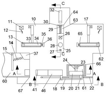
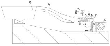
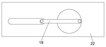
[0020] refer to Figure 1-Figure 4 According to an embodiment of the present invention, a metal parts grinding device includes a casing 10, a control chamber 63 communicating with the outside world is provided in the casing 10, and a control chamber 63 communicating with the outside world is provided in the lower end wall of the control chamber 63. The connecting rod chamber 61, the front end surface of the casing 10 is slidingly connected with two symmetrical sleeve rods 33, the sleeve rods 33 are provided with a moving chamber 62, the upper end surface of the casing 10 is provided with a shock plate 49, the The shock plate 49 is fixedly connected with a guide rail 50, the guide rail 50 is provided with an orientation cavity 60 communicating with the outside wo...


PUM


Abstract

The invention discloses a metal part polishing device which comprises a machine shell, a control cavity is formed in the machine shell, a connecting rod cavity is formed in the lower end wall of the control cavity, a vibration disc is arranged on the upper end face of the machine shell, a guide rail is fixedly connected to the vibration disc, and a clamping mechanism, an edge polishing mechanism and a control mechanism are arranged in the machine shell. Through a reversing block and a polishing block, polishing of holes in metal parts can be completed; the reversing block can also complete steering of the metal parts, so that use of complex mechanisms is reduced; the reversing block and the polishing block are controlled through a detection lamp, so that the mechanisms are simplified,and manual re-polishing of the mechanisms is reduced; and the metal parts can be poured automatically and regularly through a designed timing spring, and after one metal part is polished, only one metal part is ensured to move to the position where the metal parts need to move, so that new metal parts are prevented from being directly accumulated at the outlet.

Description

technical field [0001] The invention relates to the field of grinding and polishing, in particular to a grinding device for metal parts. Background technique [0002] At present, most of the grinding of metal parts is done manually, or the edges are polished by machines, while the holes of metal parts are still polished manually. If the metal parts are not polished, it is easy to cause harm to the installer, and the grinding is done manually. , It is easy to be injured for novices, and manual grinding takes a long time, the efficiency is low, and it is difficult to achieve complete grinding. The current manual and machine-assisted grinding is mostly to manually clamp the metal parts through the fixture, and then send them to be polished. Grinding on the machine, after polishing one side, manually change the direction, and continue grinding. This kind of grinding must be manually participated and monitored in real time, and the efficiency is not high enough. Contents of the...

Claims


Application Information

Patent Timeline
Patent Type & Authority Applications(China)
IPC IPC(8): B24B27/00B24B9/04B24B5/48B24B19/00B24B41/00B24B41/02B24B41/06B24B47/12B24B47/14B24B41/04B24B49/12B24B51/00
CPCB24B27/0076B24B9/04B24B5/48B24B19/00B24B41/005B24B41/02B24B41/06B24B47/12B24B49/12B24B41/04B24B47/14B24B51/00
Inventor 王婷
Owner 王婷
Why Eureka
Eureka Blog
Learn More