
Discharging door mechanism, stirring device and discharging control method

A control method and technology for a discharge door, applied in the direction of the discharge device, etc., can solve the problems of one-side discharge of the discharge door and the inability to adjust the gap, and achieve the effect of small wear and long service life.

Pending Publication Date: 2022-02-08
SANY AUTOMOBILE MFG CO LTD
View PDF0 Cites 0 Cited by
  • Summary
  • Abstract
  • Description
  • Claims
  • Application Information

AI Technical Summary

Problems solved by technology

[0004] One of the objectives of the present invention is to provide a discharge door mechanism and a stirring device to solve the defect in the prior art that the gap between the discharge door and the shell cannot be adjusted after the discharge door is worn
[0005] Another object of the present invention is to provide a discharge control method to solve the problem in the prior art that the discharge door can only perform one-sided discharge

Method used


Image

  • Discharging door mechanism, stirring device and discharging control method
  • Discharging door mechanism, stirring device and discharging control method
  • Discharging door mechanism, stirring device and discharging control method

Examples


Embodiment Construction

[0049] In order to make the purpose, technical solutions and advantages of the present invention clearer, the technical solutions in the present invention will be clearly and completely described below in conjunction with the accompanying drawings in the present invention. Obviously, the described embodiments are part of the embodiments of the present invention , but not all examples. Based on the embodiments of the present invention, all other embodiments obtained by persons of ordinary skill in the art without creative efforts fall within the protection scope of the present invention.

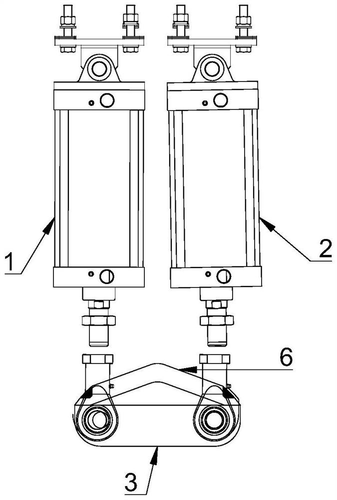
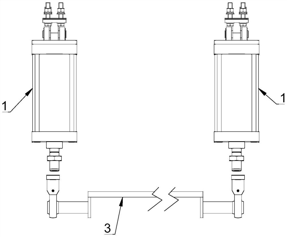
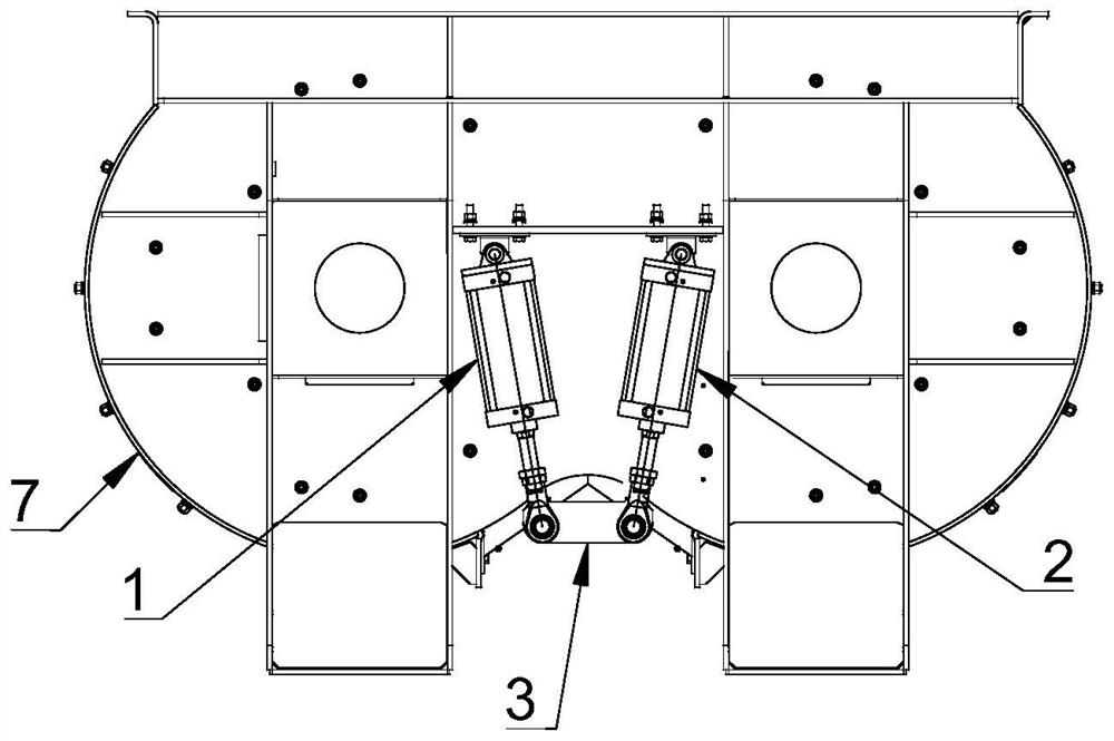
[0050] Combine below Figure 1 to Figure 8 Describe the discharge door mechanism in the embodiment provided by the present invention.

[0051] Specifically, the discharge door mechanism includes a first linear drive mechanism 1 , a second linear drive mechanism 2 and a door body 3 .

[0052] refer to figure 1 , figure 2 As shown, wherein, the door body 3 has a first side and a second sid...


PUM


Abstract

The invention relates to the technical field of concrete stirring, and provides a discharging door mechanism, a stirring device and a discharging control method. The discharging door mechanism comprises a first linear driving mechanism, a second linear driving mechanism and a door body. The door body comprises a first side and a second side which are oppositely arranged, the first end of the first linear driving mechanism and the first end of the second linear driving mechanism are rotatably connected to the first side and the second side of the door body respectively, and the second end of the first linear driving mechanism and the second end of the second linear driving mechanism are rotatably arranged; the door body is used for being arranged at a discharging port of the stirring device so as to block and open the discharging port. Under the driving action of the first linear driving mechanism and the second linear driving mechanism, the door body is tightly pressed at the discharge port, so that the door body and the discharge port can be always kept better fit. Compared with a fixed shaft type discharging door in the prior art that the rotating abrasion is serious, the discharging door provided by the invention is smaller in abrasion and longer in service life.

Description

technical field [0001] The invention relates to the technical field of concrete mixing, in particular to a discharge door mechanism, a stirring device and a discharge control method. Background technique [0002] The discharge door of existing concrete device is mainly fixed shaft type discharge door. Specifically, the door body has an arc-shaped structure, and the door body is rotatably arranged on the discharge port of the casing through a fixed rotating shaft, so as to block and open the discharge port. This fixed shaft type discharge door mainly opens the discharge port by rotating, the gap between the door body and the housing cannot be adjusted, the door body and the housing are easy to wear, and the seal is not tight after a period of use. [0003] Therefore, how to solve the problem in the prior art that the gap between the discharge door and the housing cannot be adjusted after it is worn is a technical problem urgently needed by those skilled in the art. Content...

Claims


Application Information

Patent Timeline
IPC IPC(8): B28C7/16
CPCB28C7/162
Inventor 刘伟曦邹祥周浩
Owner SANY AUTOMOBILE MFG CO LTD
Learn More