
Seat rotating mechanism

A technology of rotating mechanism and seat, applied in the direction of movable seat and so on

Active Publication Date: 2022-02-08
CHANGCHUN FAWAY ADIENT AUTOMOTIVE SYST CO LTD
View PDF15 Cites 0 Cited by
  • Summary
  • Abstract
  • Description
  • Claims
  • Application Information

AI Technical Summary

Problems solved by technology

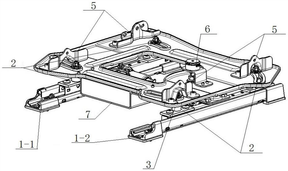
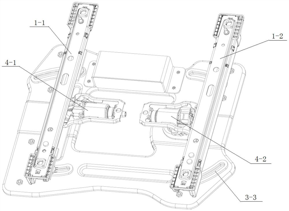
[0004] The invention provides a seat rotation mechanism, in which the left and right slide rail assemblies are respectively equipped with horizontal motors, which can realize the synchronous movement or relative movement of the two slide rails, and when the guide pins move relative to the slide rails , by sliding in the chute of the turntable to drive the turntable to rotate, so that the whole chair rotates, which solves the above-mentioned problems existing in the existing rotating seat structure

Method used


Image

  • Seat rotating mechanism
  • Seat rotating mechanism
  • Seat rotating mechanism

Examples


Embodiment Construction

[0048] The present invention will be further described in detail below in conjunction with the accompanying drawings and embodiments. It should be understood that the specific embodiments described here are only used to explain the present invention, but not to limit the present invention. In addition, it should be noted that, for the convenience of description, only some structures related to the present invention are shown in the drawings but not all structures.

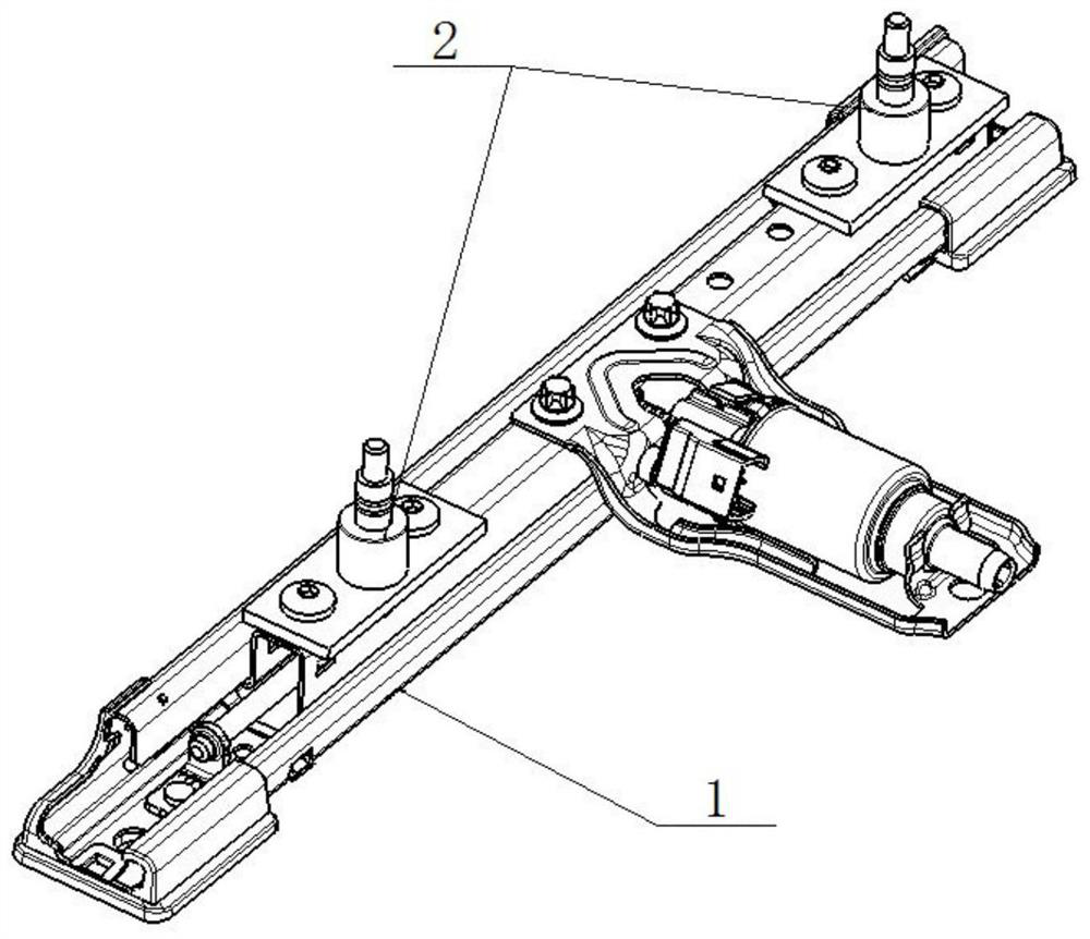
[0049] refer to figure 1 and Figure 6 , a seat rotation mechanism, including a slide rail assembly 1, a guide pin assembly and a fastener 2, a turntable assembly 3, a drive mechanism 4, a connecting bracket 5, a potentiometer 6 and a controller 7.

[0050] The driving mechanism 4 is arranged on the slide rail assembly 1, and drives the slide rail assembly 1 to move; the guide pin shaft assembly and the upper end of the matching installation fastener 2 pass through the turntable assembly 3 and along the turntable...


PUM


Abstract

The invention relates to a seat rotating mechanism comprising slide rail assemblies, a guide pin shaft assembly, a matched mounting fastener, a turntable assembly, a driving mechanism, a connecting bracket and a potentiometer; the driving mechanism drives the slide rail assemblies to move; the upper end of the guide pin shaft assembly penetrates through the turntable and slides along a turntable curve chute, and the lower end of the guide pin shaft assembly is fixed right above the slide rail assemblies; the turntable is connected with a cushion assembly through a connecting bracket; the potentiometer is arranged on the turntable, and a rotating shaft end is connected with a slide rail support welding bolt assembly. And a controller is connected with the driving mechanism and the potentiometer. The slide rail assemblies are driven by the driving mechanism to move, when the left slide rail assembly and the right slide rail assembly generate relative movement, the guide pin shaft assembly moves front and back along with the slide rail assemblies and slides in the arc-shaped sliding groove to drive the turntable to rotate, so that the whole chair rotates, and the situation that the complexity and controllability of a system are increased due to introduction of a rotating connecting rod is avoided; and meanwhile, the problem that the Z-direction height is excessively increased due to rotation of a gear meshing mechanism is solved.

Description

technical field [0001] The invention belongs to the technical field of automobiles, in particular to a seat rotation mechanism. Background technique [0002] Along with popularizing of automobile in daily life, automobile has become a kind of important means of transportation for people to travel. The car seat is an important part of the car, which is related to the comfort and safety of the car. At present, the sales of seats equipped with swivel functions are on the rise. The application of swivel functions not only brings convenient driving experience to passengers, smooth communication status, comfortable sleep mode, but also provides a fashionable technological atmosphere. [0003] However, the existing swivel seats are complex in structure, high in manufacturing cost, inconvenient to operate, low in swivel accuracy, and have too much height increase in the Z direction, and currently no electric stepless swivel function seat has been applied in mass-produced products. ...

Claims


Application Information

Patent Timeline
Patent Type & Authority Applications(China)
IPC IPC(8): B60N2/14
CPCB60N2/14
Inventor 战磊杨姣尚尔原
Owner CHANGCHUN FAWAY ADIENT AUTOMOTIVE SYST CO LTD
Learn More