Self-climbing formwork and core tube binding construction method
A core tube and formwork technology, which is applied in the field of self-climbing formwork and core tube binding construction, can solve the problems of labor and construction period waste, idle work, and inability to form flow construction, etc.
- Summary
- Abstract
- Description
- Claims
- Application Information
AI Technical Summary
Problems solved by technology
Method used
Image
Examples
Embodiment 1
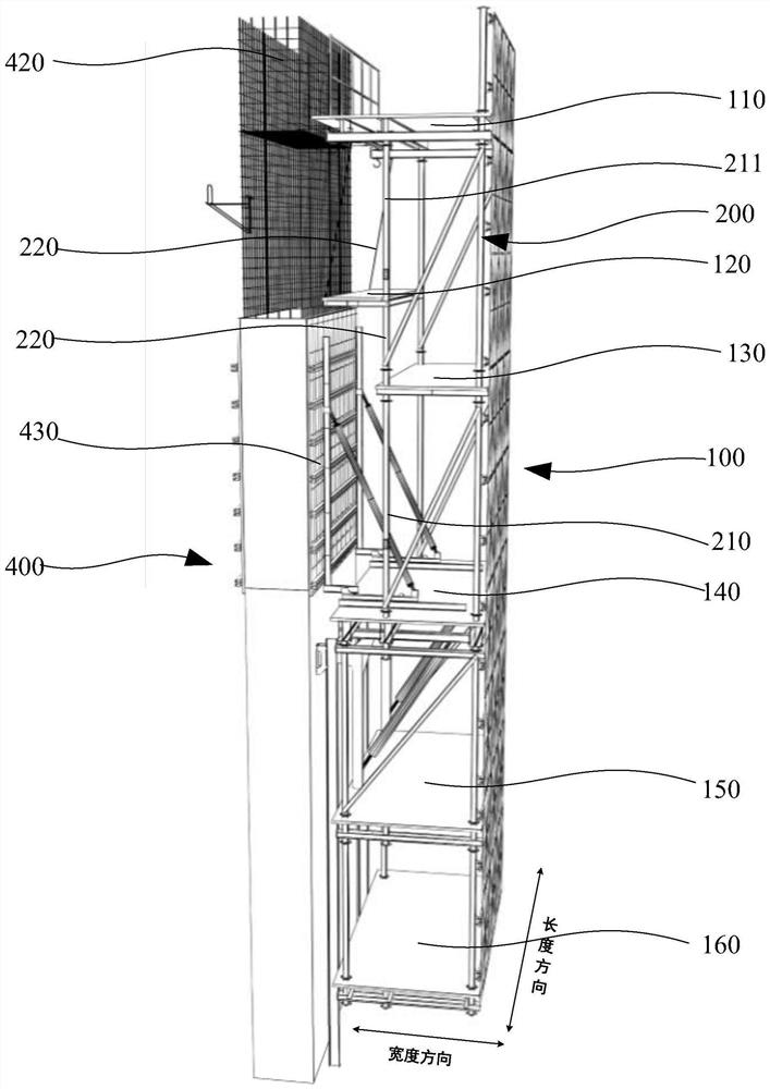
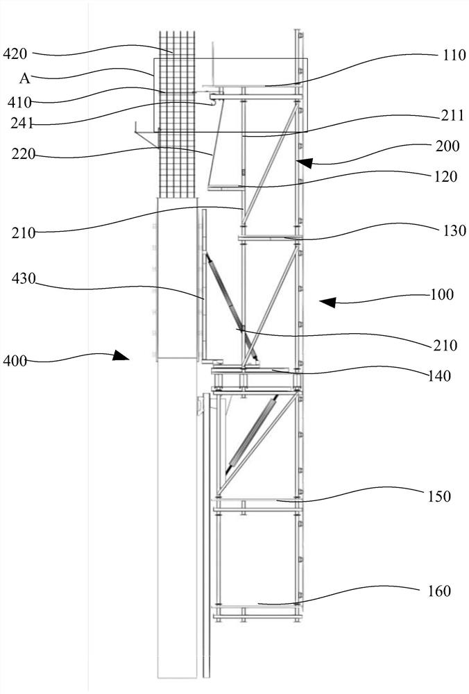
[0038] see figure 1 , figure 2 and image 3 , this embodiment provides a self-climbing formwork for the construction of the core tube 400 . The self-climbing formwork frame includes a lifting frame 100. The lifting frame 100 is installed on the side of the core tube 400 and can climb upwards. The lifting frame 100 includes a top platform 110, a reinforcement platform 120, and a transition platform 130 arranged at intervals from top to bottom. And template operation platform 140. The top platform 110 is used for storing the reinforcing bars 420 and binding the reinforcing bars 420 , the reinforcing bar platform 120 is used for binding the reinforcing bars 420 , the transition platform 130 and the formwork operation platform 140 are used for the construction of the formwork 430 .
[0039] Since the self-climbing formwork frame provided by the embodiment of the present application provides the top platform 110 and the reinforcement platform 120, during construction, the reinf...
Embodiment 2
[0045] Such as figure 2 and image 3 As shown, on the basis of the first embodiment, this embodiment proposes a setting method of the tendon-tying platform 120 . The lifting frame 100 also includes a connection assembly 200, the connection assembly 200 includes a plurality of uprights 210, a plurality of uprights are connected between the top platform 110 and the transition platform 130, and a plurality of uprights are also connected between the transition platform 130 and the formwork operation platform 140 Upright column 210, the upright column 210 located between the top platform 110 and the transition platform 130 and close to the side of the core tube 400 is set as a fixed column 211, the rib-tying platform 120 is rotationally connected with at least two adjacent fixing columns 211, and the ribs are tied The platform 120 is located on the side of the fixed column 211 close to the core tube 400. The rib-tying platform 120 can be turned away from the core tube 400. A fixi...
Embodiment 3
[0051] Such as Figure 4 and Figure 5 As shown, this embodiment proposes an arrangement method of the tension member 300 on the basis of the first or second embodiment. The connection assembly 200 further includes a plurality of crossbeams 230 . The downward facing surface of the top platform 110 is provided with crossbeams 230 along the length direction of the top platform 110 , and the plurality of crossbeams 230 are arranged at intervals along the width direction of the top platform 110 . The lifting frame 100 also includes a plurality of tie rod assemblies 300, which are arranged at intervals between the beam 230 and the ladder bars 410 of the core tube 400, and the tie bar assemblies 300 are used to limit the steel bars 420 abutting against the ladder bars 410 Tilt away from the top platform 110 .
[0052] Specifically, the beam 230 is arranged along the length direction of the roof platform 110 on the downward side of the roof platform 110, and a plurality of beams 23...
PUM
 Abstract
Description
Claims
Application Information
 - R&D
- Intellectual Property
- Life Sciences
- Materials
- Tech Scout
- Unparalleled Data Quality
- Higher Quality Content
- 60% Fewer Hallucinations
Browse by: Latest US Patents, China's latest patents, Technical Efficacy Thesaurus, Application Domain, Technology Topic, Popular Technical Reports.
© 2025 PatSnap. All rights reserved.Legal|Privacy policy|Modern Slavery Act Transparency Statement|Sitemap|About US| Contact US: help@patsnap.com


