Testing tool for resistance of inner conductor and outer conductor of coaxial cable
A coaxial cable and conductor resistance technology, applied in measuring devices, measuring resistance/reactance/impedance, measuring electricity, etc., can solve the problems of wire damage, easy accidental hand injury, etc., and achieve high accuracy and high safety.
- Summary
- Abstract
- Description
- Claims
- Application Information
AI Technical Summary
Problems solved by technology
Method used
Image

Examples
Embodiment 1
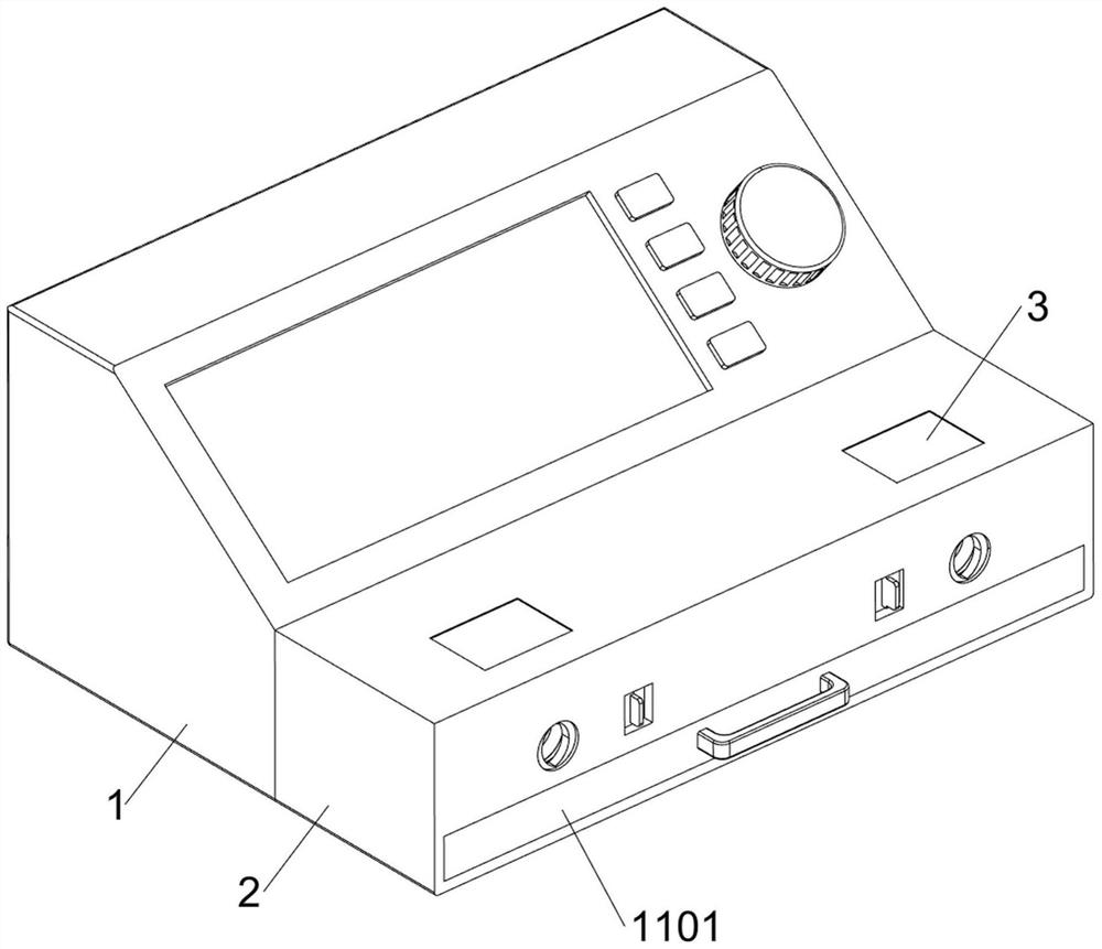
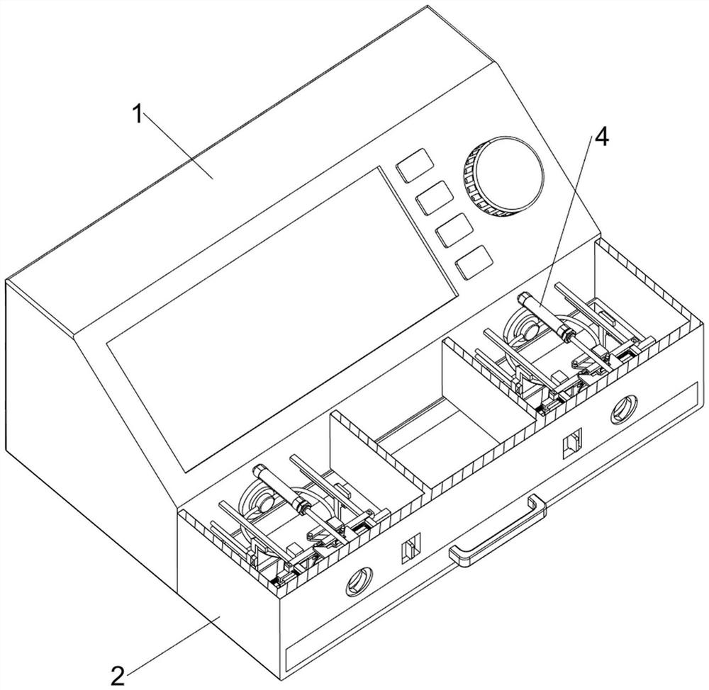
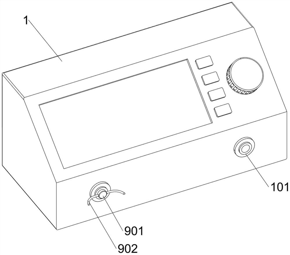
[0036] A test tool for the resistance of the inner and outer conductors of a coaxial cable, such as Figure 1-Figure 17 As shown, it includes a testing machine 1, a port 101, a housing 2, a glass plate 3, an electric push rod 4, a special-shaped block 5, a support sleeve 6, a support assembly 7, a cutting ring assembly 8, a test assembly 9 and a pulling assembly 10, The lower front side of the testing machine 1 is provided with a housing 2, and the lower front side of the testing machine 1 is provided with ports 101 symmetrically left and right. The ports 101 are all located inside the housing 2, and the left and right sides of the top of the housing 2 are provided with glass plates 3. , people can observe the test situation of the coaxial cable through the glass plate 3, the lower front side of the testing machine 1 is equipped with electric push rods 4 symmetrically left and right, the electric push rods 4 are all located inside the housing 2, and the electric push rods 4 are...
PUM
 Abstract
Description
Claims
Application Information