
Dense net stent

A dense mesh and mesh technology, applied in the field of dense mesh stents, can solve problems such as infarction and aneurysm cavity rupture, and achieve the effect of preventing thrombosis

Pending Publication Date: 2022-02-11
张葳琳
View PDF0 Cites 0 Cited by
  • Summary
  • Abstract
  • Description
  • Claims
  • Application Information

AI Technical Summary

Problems solved by technology

[0004] Therefore, the technical problem to be solved by the present invention is to overcome the dense mesh stent in the prior art. When in application, when the blood flow velocity is relatively high, part of the blood flow will pass through the vascular stent and impact towards the aneurysm cavity. Under the action of force, the aneurysm cavity will rupture, which will lead to the defect of infarction, thus providing a dense mesh stent

Method used


Image

  • Dense net stent
  • Dense net stent
  • Dense net stent

Examples


Embodiment 1

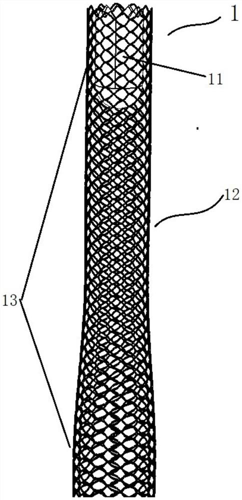
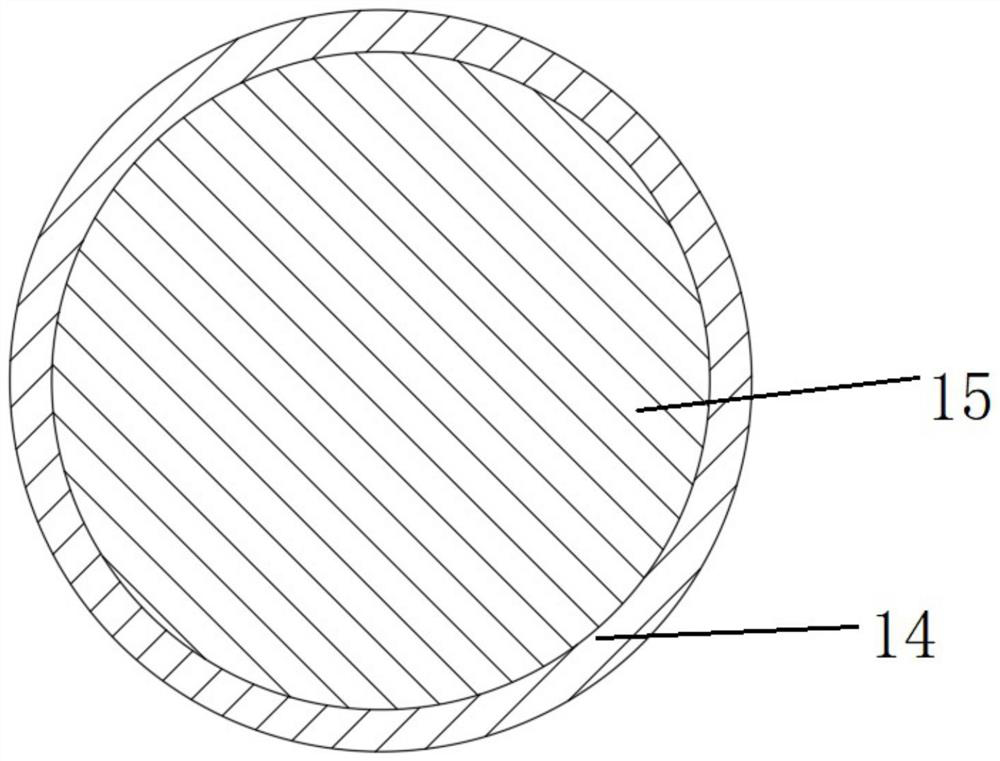
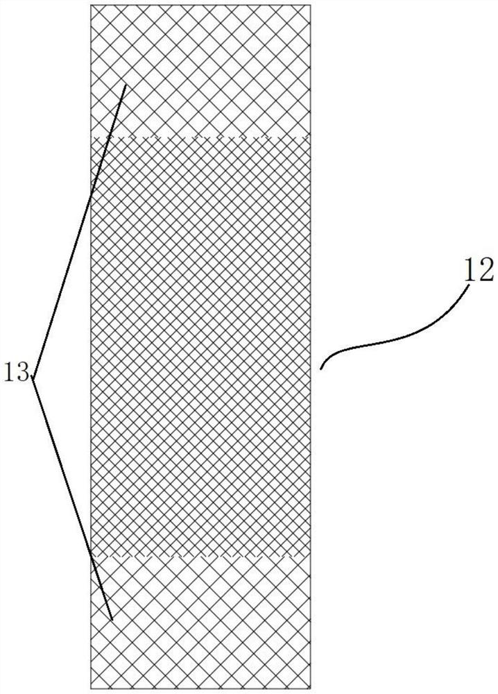
[0037] This embodiment describes a dense mesh bracket, see Figure 1-Figure 4 , the dense mesh stent includes a stent body 1, the stent body 1 is arranged in the shape of a mesh tube, and the stent body 1 has a rhombus-shaped mesh 11, specifically, the stent body 1 is provided with a mesh suitable for corresponding to the aneurysm cavity The dense mesh area 12, and symmetrically arranged on both sides of the dense mesh area 12, the sparse mesh area 13 adjacent to the dense mesh area 12, the density of the mesh 11 of the dense mesh area 12 is greater than any one of the sparse mesh areas 13 The mesh 11 density, and the area of ​​the mesh 11 that will be located in the dense mesh area 12 is less than any one of the mesh 11 areas located in the sparse mesh area 13, so that the mesh 11 of the dense mesh area 12 on the support body 1 is relatively The meshes 11 in the mesh area 13 are denser.

[0038] The mesh density here refers to the number of meshes per unit area.

[0039] In...

Embodiment 2

[0046] This embodiment describes a dense-mesh stent, which is made of 96 ingots. After the stent body 1 expands, the diameters of the two sparse-mesh regions 13 and the corresponding diameters of the dense-mesh region 12 can be 3- 6mm, the metal coverage rate of the mesh area 13 is 35.5%-38.09%, the height of the mesh holes 11 on it is 0.137mm-0.141mm, the radial spacing is 0.202mm-0.189mm, and the axial spacing is 0.186mm- 0.194mm.

[0047] The metal coverage of the dense mesh area 12 can be 55%-57.31%, the height of the diamond-shaped mesh 11 is 0.069mm-0.058mm, the radial distance is 0.166mm-0.157mm, and the axial distance is 0.076mm-0.066mm , where the metal coverage of the stent body 1 is relatively high, and the density of the mesh 11 is relatively high.

Embodiment 3

[0049] This embodiment describes a dense mesh bracket, see Figure 5 , the dense mesh stent is used for a single aneurysm 2, the dense mesh area 12 of the dense mesh stent is positioned at the position of the aneurysm 2 and attached to the blood vessel wall, and the metal coverage of the dense mesh area 12 is set at 15%. -20%.


PUM

PropertyMeasurementUnit
Diameteraaaaaaaaaa
Heightaaaaaaaaaa
Axial spacingaaaaaaaaaa

Abstract

The invention relates to the field of medical instruments, and provides a dense net stent which comprises a stent body, the stent body is arranged in a net tube shape and provided with diamond-shaped meshes, a dense net area suitable for corresponding to an aneurysm cavity and sparse net areas symmetrically arranged on the two sides of the dense net area and adjacent to the dense net area are arranged on the stent body, and the dense net area and the sparse net areas are arranged on the stent body. The mesh density of the dense net area is greater than that of any sparse mesh area; and / or the area of the meshes located in the dense net area is smaller than the area of any mesh located in the sparse net area. When the dense net area is attached to the blood vessel wall, the dense net area is suitable for being arranged at the position corresponding to an aneurysm cavity, then when blood flow with the high blood flow speed rushes to the position of the aneurysm cavity, part of blood flow permeating and impacting the inner wall of the aneurysm cavity can be reduced. Meanwhile, due to the fact that the mesh density at the position is larger, and the mesh area at the position is smaller. The speed of blood flow permeating into the aneurysm cavity can be reduced, so that the defect that the aneurysm cavity is broken due to the fact that blood impacts the aneurysm cavity can be overcome.

Description

technical field [0001] The invention relates to the technical field of medical devices, in particular to a dense mesh bracket. Background technique [0002] An aneurysm is a common blood vessel defect that develops as a result of weakening of the vessel wall and subsequent swelling and dilation of the vessel wall. The blood vessel walls gradually thin and, in some places, may rupture due to the constant pressure of the blood flow. [0003] In the prior art, the dense mesh stent is mainly used to change the direction of blood flow, thereby avoiding the impact of blood on the inner wall of the aneurysm, thereby achieving the purpose of treating vascular aneurysms. However, in practical applications, when the dense mesh stent is attached to the On the inner wall of the corresponding aneurysm, although the direction of blood flow is changed, part of the blood flow will pass through the vascular stent and impact towards the aneurysm cavity when the blood flow velocity is high. ...

Claims


Application Information

Patent Timeline
IPC IPC(8): A61F2/90
CPCA61F2/90
Inventor 张葳琳
Owner 张葳琳
Learn More