Bending and angle wrapping die and bending and angle wrapping method

A mold and corner wrapping technology, applied in the field of bending wrapping die and corner wrapping, can solve the problems of hidden danger of manipulator, complicated structure of sliding block, complicated structure of door shell, etc., so as to reduce production cost and be suitable for popularization and use. , the effect of improving the appearance quality

Active Publication Date: 2022-02-11
QINGDAO HAIER MOLDS
View PDF13 Cites 1 Cited by
  • Summary
  • Abstract
  • Description
  • Claims
  • Application Information

AI Technical Summary

Problems solved by technology

[0002] At present, the door shells of some high-end products all use hidden end covers, resulting in a more complicated structure of the product door shells than ordinary products, adding flanging at the end and other parts; while the current product door shells are generally produced through blanking, flanging, The four processes of U-shaped bending (bending) and corner wrapping. The corner wrapping knife forming method of the current bending mold is to use the guide rail to slide in one direction. The corner wrapping block needs to be relatively large and has a complex structure and poor stability. The large area increases the area in contact with the plate. In order to achieve the purpose of synchronous wrapping, no matter what the bending height is, the height of the wrapping on both sides is the same, which will cause the small part of the wrapping edge to contact the sheet too much, resulting in Paint peeling and film breakage on corners caused by long friction time
[0003] The Chinese invention patent with the application number of 201810627772.6 discloses a refrigerator door shell bending and wrapping mold. The typical structure of the wrapping knife is a 45° wrapping slider structure. Difficult, long-term impact force will cause problems such as fracture, which will cause safety hazards to the operation of continuous production manipulators. At the same time, there will be local skin cracks at the fillet forming positions of VCM\PCM\3D printing plates and other plates
[0004] The purpose of the present invention is to solve the puzzlement of the above mold problems and product quality problems exposed in the long-term production process

Method used


Image

  • Bending and angle wrapping die and bending and angle wrapping method
  • Bending and angle wrapping die and bending and angle wrapping method
  • Bending and angle wrapping die and bending and angle wrapping method

Examples


Embodiment 1

[0043] Such as Figure 1-5 As shown, the present invention introduces a kind of bending corner wrapping mold, which includes a first mold 2 and a second mold 3 which are arranged oppositely. The first mold 2 is equipped with a corner wrapping knife 1 towards the side of the second mold 3, and the corner wrapping knife 1 is rotatably connected with the first mold 2 through the first fixed shaft 13. Through the above settings, the plate is wrapped in the form of rotating angle wrapping, thereby reducing the contact area between the mold and the plate, reducing the friction between the mold and the plate, and avoiding the corner wrapping caused by the excessive friction between the plate and the mold The problem of paint peeling and film breaking. The side of the first mold 2 facing the second mold 3 is also equipped with a corner-wrapping knife fixing seat 24 , and a corner-wrapping knife fixing seat 24 is provided with a mounting hole matched with the first fixed shaft 13 . T...

Embodiment 2

[0053] Based on the corner-wrapping mold provided in the first embodiment of the present application, the second embodiment of the present application proposes another corner-wrapping knife 1 . The second embodiment is only a preferred mode of the first embodiment, and the implementation of the second embodiment will not affect the independent implementation of the first embodiment.

[0054] The second embodiment of the present invention will be further described below in conjunction with the drawings and implementation methods.

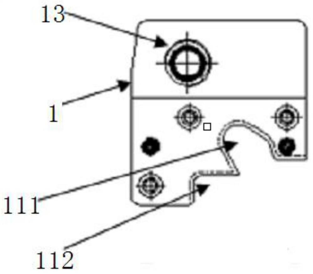
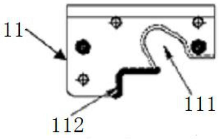
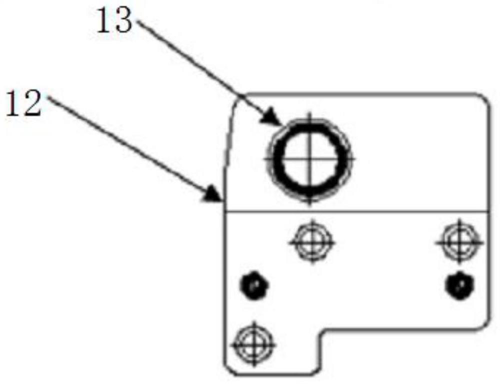
[0055] A corner-wrapping mold disclosed in this embodiment includes a corner-wrapping knife 1. The corner-wrapping knife 1 includes a corner-wrapping knife main body 11 and a corner-wrapping knife fixing seat 12. A first fixed shaft is arranged on the corner-wrapping knife fixing seat 12. 13 is rotatably connected with the first mold 2, and the angle-wrapping knife fixing seat 12 is connected with the first mold 2 only by one fixed shaft, so that the...

Embodiment 3

[0060] This embodiment discloses a method for bending and wrapping a corner-wrapping mold. A bending knife 25 is installed on the side of the first mold 2 facing the second mold 3, and the bending knife 25 is located on the side of the corner-wrapping knife 1. Before the corner wrapping program is carried out, the bending knife 25 first bends the plate. The concrete bending angle wrapping method in this implementation includes the following steps:

[0061] 1) The mold starts to run, and the first mold 2 and the second mold 3 are reset;

[0062] 2) The first mold 2 descends, the first stripping plate 21 provided on the first mold 2 presses the plate, the first mold 2 continues to descend, and the bending knife 25 provided on the first mold 2 begins to perform the bending procedure on the plate;

[0063] 3) The bending procedure is completed, the first mold 2 continues to descend, the limit shaft 211 set on the first stripping plate 21 enters the guide groove 111 set on the cor...


PUM


Abstract

The invention discloses a bending and angle wrapping die and a bending and angle wrapping method. The bending and angle wrapping die comprises a first die body and a second die body which are oppositely arranged, an angle wrapping knife is installed on the side, facing the second die body, of the first die body, and the angle wrapping knife is rotationally connected with the first die body through a first fixing shaft; the bending and angle wrapping method comprises the steps that the dies start to run, and the first die and the second die are reset; the first die moves downwards, a first stripping plate on the first die presses the plate, the first die continues to move downwards, and a bending knife on the first die starts to bend the plate; and after the bending procedure is completed, the first die continues to move downwards, a limiting shaft on the first stripping plate enters a guide groove in the angle wrapping knife, the angle wrapping knife rotates along a track set by the first fixing shaft and the limiting shaft, and the angle wrapping procedure is completed. Through the arrangement, a rotary angle wrapping method is adopted, so that the contact area between the angle wrapping knife and the plate is reduced, the friction between the angle wrapping knife and the plate is reduced, and the problems of film rupture and paint peeling of the plate are solved.

Description

technical field [0001] The invention relates to the technical field of moulds, in particular to a corner-bending mold and a corner-bending method. Background technique [0002] At present, the door shells of some high-end products all use hidden end covers, resulting in a more complicated structure of the product door shells than ordinary products, adding flanging at the end and other parts; while the current product door shells are generally produced through blanking, flanging, The four processes of U-shaped bending (bending) and corner wrapping. The corner wrapping knife forming method of the current bending mold is to use the guide rail to slide in one direction. The corner wrapping block needs to be relatively large and has a complex structure and poor stability. The large area increases the area in contact with the plate. In order to achieve the purpose of synchronous wrapping, no matter what the bending height is, the height of the wrapping on both sides is the same, w...

Claims


Application Information

Patent Timeline
Patent Type & Authority Applications(China)
IPC IPC(8): B21D37/10B21D37/12B21D19/08B21D21/00
CPCB21D37/10B21D37/12B21D19/08B21D21/00
Inventor 魏克宁刘鉴桓李杰郝建财王鑫周应孜
Owner QINGDAO HAIER MOLDS
Why Eureka
Try Eureka