
Bar optical coating overturning clamp

A technology of optical coating and flipping fixtures, which is applied in gaseous chemical coating, manufacturing tools, sputtering coating, etc., and can solve problems such as fixation, single structure, and reduced work efficiency

Pending Publication Date: 2022-02-11
桂林芯隆科技有限公司
View PDF7 Cites 1 Cited by
  • Summary
  • Abstract
  • Description
  • Claims
  • Application Information

AI Technical Summary

Problems solved by technology

[0004] The purpose of the present invention is to provide a BAR strip optical coating flip fixture, which aims to solve the problem that the traditional fixture structure in the prior art is single and fixed, and the flipping of the Bar strip cannot be realized, and manual secondary adjustment is required, resulting in work efficiency. Reduced technical issues

Method used


Image

  • Bar optical coating overturning clamp
  • Bar optical coating overturning clamp
  • Bar optical coating overturning clamp

Examples


Embodiment Construction

[0030] Embodiments of the present invention are described in detail below, examples of which are shown in the drawings, wherein the same or similar reference numerals designate the same or similar elements or elements having the same or similar functions throughout. The embodiments described below by referring to the figures are exemplary and are intended to explain the present invention and should not be construed as limiting the present invention.

[0031] In describing the present invention, it should be understood that the terms "length", "width", "upper", "lower", "front", "rear", "left", "right", "vertical", The orientation or positional relationship indicated by "horizontal", "top", "bottom", "inner", "outer", etc. are based on the orientation or positional relationship shown in the drawings, and are only for the convenience of describing the present invention and simplifying the description, rather than Nothing indicating or implying that a referenced device or element...


PUM


Abstract

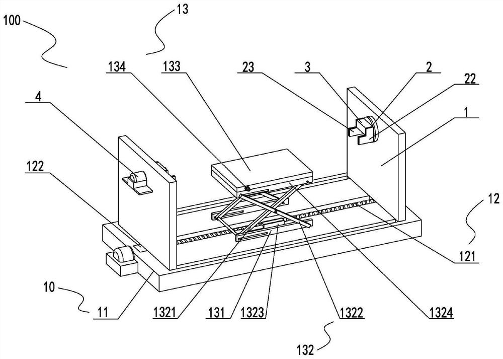
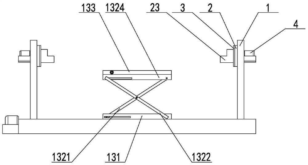
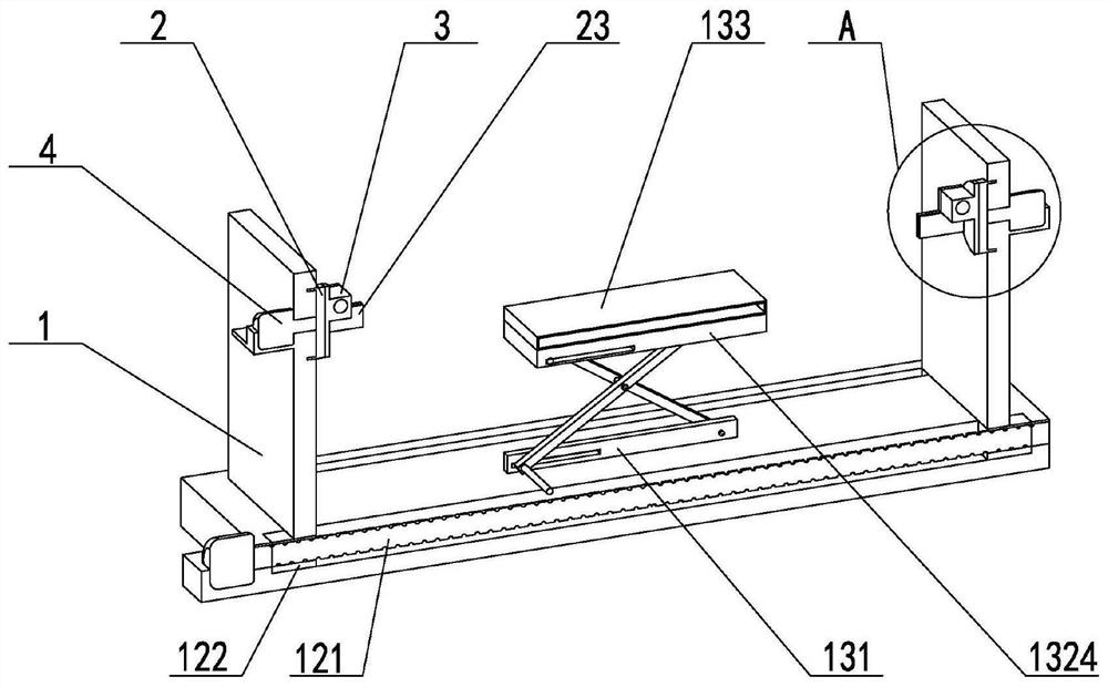
The invention belongs to the technical field of bar processing and relates to a bar optical coating overturning clamp. Supporting plates are supported through a supporting assembly, the number of the supporting plates is two; the two supporting plates are oppositely arranged on the supporting assembly; two rotating tables are provided and are correspondingly installed on the supporting plates in a sliding mode respectively; two installing seats are provided and are correspondingly installed on the rotating tables respectively; two power pieces are provided and are correspondingly fixed to the supporting plates respectively; the output ends of the power pieces are fixedly connected with the rotating tables, so that the the power pieces drive the rotating tables to rotate and drive the installing seats to rotate; and clamping assemblies are mounted on the installing seats and used for clamping a bar and rotating along with the installing seats, so that the overturning of the bar can be realized, machining is convenient, and the machining efficiency is improved.

Description

technical field [0001] The invention relates to the technical field of bar bar processing, in particular to a bar bar optical coating flip fixture. Background technique [0002] The optical coating of the BAR bar is to coat the corresponding optical dielectric film layer on both ends of the BAR bar. The existing method is to clamp the Bar bar with a clamp, and then move and place it to perform the coating operation. [0003] However, the traditional fixture structure is single and fixed, and the bar cannot be turned over, and a second manual adjustment is required, resulting in a decrease in work efficiency. Contents of the invention [0004] The purpose of the present invention is to provide a BAR strip optical coating flip fixture, which aims to solve the problem that the traditional fixture structure in the prior art is single and fixed, and the flipping of the Bar strip cannot be realized, and manual secondary adjustment is required, resulting in work efficiency. Redu...

Claims


Application Information

Patent Timeline
Patent Type & Authority Applications(China)
IPC IPC(8): C23C14/50C23C16/458B25B11/00
CPCC23C14/505C23C16/4581B25B11/00
Inventor 黄祥恩李升儒匡嘉乐
Owner 桂林芯隆科技有限公司
Learn More